Showing posts with label is-is. Show all posts

Monday, March 19, 2012

IS-IS Route Leaking

Packets destined to other L1 areas are routed to the nearest L1/L2 router and to be forwarded to the destination area. Routing to the nearest L1/L2 router can lead to suboptimal routing when the shortest path to the destination area is via a different L1/L2 router. Route leaking is a mechanism for leaking or redistributing L2 information into L1 areas in order to reduce suboptimal routing. By having more details about the inter-area routes, an L1 router is able to make a better choice upon which L1/L2 router to forward the packets to a particular destination area.

RFC 2966 – Domain-wide Prefix Distribution with Two-Level IS-IS defines route leaking for use with the 6-bit narrow metric TLV types 128 and 130; while RFC 5305 – IS-IS Extensions for Traffic Engineering defines route leaking for use with the 32-bit wide metric TLV type 135. Both RFCs define an Up/Down bit to indicate whether or not the route advertised in the LSP has been leaked. An Up/Down bit of 0 indicates that a route was originated within an L1 area; while L1/L2 routers set the Up / Down bit to 1 for prefixes or routes that were derived from L2 routing and advertised into L1 LSPs that get propagated into the L1 area. The Up/Down bit is used to prevent routing loops. An L1/L2 router never readvertises any L1 route with the Up/Down bit set back into the L2 backbone.

The Up / Down bit for IS-IS Route Leaking

The redistribute isis ip level-2 into level-1 distribute-list {100199} IS-IS router subcommand implement IS-IS route leaking. An IP extended access list must be defined to match the routes that are to be leaked from L2 into L1. The metric-style wide IS-IS router subcommand is optional but recommended.
Note: If wide-style metric is not enabled, the metric in the TLV will be interpreted wrongly – more than 63! Because the Up/Down bit is also being interpreted along with the 6-bit metric. lolz

Cisco documentations mentioned that the command syntax differs for 12.0S and 12.2S Cisco IOS releases, which uses the advertise ip l2-into-l1 {100199} IS-IS router subcommand. Those releases only support route leaking using TLV type 135; therefore the metric-style wide IS-IS router subcommand must be configured when implementing route leaking.
Note: Recent 12.0S and 12.2S Cisco IOS releases use the redistribute command to implement route leaking.

IS-IS Route Leaking

In the sample scenario above, RT1 routes packets destined to 192.168.2.0/24 to the nearest L1/L2 router – RT3 by default. However, that route is not the most optimal path.

Below shows the IP routing table on RT1 after implemented route leaking on RT2 and RT3.
RT1 will now use the path via RT2 instead of RT3 to reach 192.168.2.0/24. Route leaking allows RT1 to determine the true cost to reach 192.168.2.0/24 and forward packets accordingly.
RT1#sh ip route

Gateway of last resort is 13.13.13.3 to network 0.0.0.0

     12.0.0.0/24 is subnetted, 1 subnets
C       12.12.12.0 is directly connected, FastEthernet0/0
C    192.168.1.0/24 is directly connected, Loopback0
     13.0.0.0/24 is subnetted, 1 subnets
C       13.13.13.0 is directly connected, FastEthernet1/0
i ia 192.168.2.0/24 [115/35] via 12.12.12.2, FastEthernet0/0
i*L1 0.0.0.0/0 [115/10] via 13.13.13.3, FastEthernet1/0
RT1#

Below shows the L1 LSP generated by RT2 for the leaked route – 192.168.2.0/24.
Note that wide-style metric has been enabled on all routers in this sample scenario.
RT1#sh isis database RT2.00-00 detail


IS-IS Level-1 LSP RT2.00-00
LSPID                 LSP Seq Num  LSP Checksum  LSP Holdtime      ATT/P/OL
RT2.00-00             0x00000005   0x6884        1194              1/0/0
  Area Address: 49.0001
  NLPID:        0xCC
  Hostname: RT2
  IP Address:   12.12.12.2
  Metric: 15         IP 12.12.12.0/24
  Metric: 15         IS-Extended RT2.01
  Metric: 20         IP-Interarea 192.168.2.0/24
RT1#

Leaked routes are called inter-area routes, which shown as IP-Interarea in the IS-IS LSDB and marked with an ia designation in the IP routing table.

2 common BGP practices benefit greatly from the route leaking ability:
  • One criterion used in the BGP path-selection process is the IGP cost to the BGP next-hop address. Many ISPs rely on the IGP metric to choose the best path through their ASs. This practice is known as shortest exit routing.
  • Another common practice is to use the IGP metric for the value of the MED when advertising routes to other ASs. This provides the ability to request other ASs to use the shortest path through the AS when making routing decisions.
Before route leaking, if multiple areas were used within the AS, the IS-IS metric did not represent the true internal cost and did not work well with either of these practices. Leaking routes for all the BGP next-hop addresses implements a multiarea hierarchy while maintaining accurate end-to-end IGP metrics.

In MPLS VPN environments, reachability information for the loopback addresses of every Provider Edge (PE) router is needed. Leaking routes for the PE loopback addresses allows a multiarea hierarchy to be used in MPLS VPN implementations.

Route leaking can also be used to implement a crude form of traffic engineering. Leaking routes for individual addresses or services from specific L1/L2 routers control the exit point from an L1 area used to reach those addresses and services.

By default, IS-IS L1/L2 routers set the ATTached bit in their LSPs generated for their L1 areas. This original concept soon became obsolete after the route leaking capability was introduced. The ignore-attached-bit hidden IS-IS router subcommand can be configured on an L1/L2 router to ignore the ATTached bit in the LSPs from another L1/L2 router, and therefore does not install the IS-IS-learned default route into the IP routing table.

IS-IS Authentication

IS-IS supports authentication for a link, an L1 area, or a L2 domain. Routers must exchange IIHs and LSPs for the corresponding L1 and L2 routing levels using the mutually agreed passwords. Authentication is not enabled by default.

Cisco IOS supports the following 3 types of IS-IS authentication:
  • IS-IS authentication – Clear-text IS-IS authentication.
  • IS-IS HMAC-MD5 authentication – Inserts an HMAC-MD5 digest TLV in IS-IS PDUs.
  • Enhanced clear-text authentication – Clear-text IS-IS authentication using a series of authentication key chain and authentication mode commands that provide easier password management and modification.
IS-IS Interface, Area, and Domain Authentications

The isis password {passwd} [level-1 | level-2] interface subcommand configures IS-IS authentication for L1 or L2 routing on an interface in order to prevent forming adjacencies with unauthorized routers. If the routing level is not specified, the router will enable both levels and send out L1 and L2 IIHs that contain the Authentication TLV.

The area-password {passwd} [authenticate snp {send-only | validate}] IS-IS router subcommand configures an IS-IS area authentication password in order to prevent receiving false routing information from unauthorized routers. The router inserts the Authentication TLV into L1 LSPs, as well as L1 CSNPs and L1 PSNPs with the optional authenticate snp keyword.

The domain-password {passwd} [authenticate snp {send-only | validate}] IS-IS router subcommand configures the IS-IS routing domain authentication password. The router inserts the Authentication TLV into L2 LSPs, as well as L2 CSNPs and L2 PSNPs with the optional authenticate snp keyword.

IS-IS Route Summarization

Route summarization provides many advantages, which includes reducing the router resources (CPU and memory) required due to reduced routing table size, and scoping or isolating route flapping issues within an area. When a router is unaware of a change or problem in the network, its LSDB is not being updated, and SPF recalculation is not being performed. Summarization allows routers within areas to only maintain and manage internal knowledge of the areas they reside and summarize the knowledge across area boundaries.

IS-IS allows manual summarization with some limitations. IS-IS internal route summarization within an area is not viable; therefore it cannot be implemented and configured on an L1 router. Multiple L1 internal routes can be summarized between areas as a single L2 route. An L1/L2 router (area border router) is where route summarization is being implemented.

IS-IS route summarization requires extra attention when there are multiple L1/L2 routers between 2 areas. If one of them is summarizing routes, others must perform summarization too. As if one of them is advertising a summary route while others advertise the more specific routes, packets will be routed through other routers due to the most-specific prefix matching rule.

The rules for route summarization on an OSPF ABR are applicable to Integrated IS-IS.
Below lists the rules for summarizing IP routes in Integrated IS-IS:
  • L1 routes cannot be summarized within an area. [1]
  • L1/L2 routers can summarize the internal routes within their areas. The summarized routes are propagated into the L2 backbone; similar to summarization on an OSPF ABR.
  • If route summarization is configured on an L1/L2 router, the same configuration must also be implemented on all L1/L2 routers reside in the area to prevent suboptimal routing.
[1] Cisco IOS allows the configuration of the summary-address IS-IS router subcommand on an L1 router without any warning message; though it has no effect on an L1 router.

The summary-address {prefix} {mask} [level-1 | level-1-2 | level-2] [metric metric] IS-IS router subcommand creates an L1 or L2 aggregate or summarized address. External routes learned from other routing protocols can also be summarized.

level-1 Only routes redistributed into L1 are summarized with the configured prefix mask.
level-1-2 Summary routes are applied when redistributing routes into L1 and L2 IS-IS, and when L2 IS-IS advertises L1 routes as reachable in its area.
level-2 Routes learned by L1 routing are summarized into the L2 backbone with the configured prefix mask. Routes redistributed into L2 IS-IS will be summarized too.

The following line will be seen on an L1/L2 summarizing router.
i su prefix/mask [115/10] via 0.0.0.0, Null0

The i su code indicates an IS-IS summary route; while the Null route is inserted into the routing table automatically upon configuring an IS-IS summary route to prevent routing loops from occurring in case receiving packets that match the summary route but the summarizing router does not have a more-specific route.

The drawback of route summarization is that routers might have lesser information to calculate the most optimal paths for all destinations.

Thursday, March 15, 2012

Tuning and Optimizing IS-IS

The Cisco IOS IS-IS configuration that configures an L1/L2 IS-IS router by default can result in the inefficient use of router and network resources and results in suboptimal routing. Although this configuration has the advantage of allowing all routers to communicate and converge without much administrative effort, it is not the most efficient way to build an IS-IS network, because routers with the default configurations send out both L1 and L2 Hellos and maintain both L1 and L2 LSDBs. Therefore, a network administrator must know how to tune IS-IS to conserve memory and bandwidth resources (only need to maintain the LSDB and send Hellos, LSPs, and SNPs for the necessary level) to achieve efficient and optimum performance.

Tuning IS-IS

The is-type level-1 and is-type level-2-only IS-IS router subcommands specify a router to act only as an internal area (L1) router or as a backbone (L2) router respectively.
The default configuration is is-type level-1-2; this is not shown in the router configuration.

Although a router can be an L1/L2 router, it might not required to establish both L1 and L2 adjacencies over all interfaces. If the router only needs to establish adjacency with an L1 router through a particular interface, it doesn’t need to send L2 Hellos out that interface, and vice versa. It wastes router and bandwidth resources to try to establish adjacencies that do not exist. Configure an interface to send only L1 or L2 Hellos using the isis circuit-type {level-1 | level-2-only} interface subcommand to tune IS-IS in such situations. Cisco IOS attempts to establish both L1 and L2 adjacencies over an interface (level-1-2) by default.
Warning: Changing the isis circuit-type will tear down existing adjacencies over the interface.

Unlike most other IP routing protocols, Integrated IS-IS does not take account of the line speed or bandwidth when setting the link metrics. All interfaces are assigned a metric value of 10, which results in suboptimal routing for networks with links of varying types and speeds. The isis metric {metric} {level-1 | level-2} interface subcommand changes the metric value (from 1 to 63). An interface can have different L1 and L2 metric values.

Below verifies the IS-IS configuration on RT1.
It has a default route i*L1 0.0.0.0/0 to the nearest L1/L2 router – RT2.
RT1#sh ip route

Gateway of last resort is 12.12.12.2 to network 0.0.0.0

     12.0.0.0/24 is subnetted, 1 subnets
C       12.12.12.0 is directly connected, FastEthernet1/0
C    192.168.1.0/24 is directly connected, FastEthernet0/0
i L1 192.168.2.0/24 [115/20] via 12.12.12.2, FastEthernet1/0
i*L1 0.0.0.0/0 [115/10] via 12.12.12.2, FastEthernet1/0
RT1#
RT1#sh clns protocol

IS-IS Router: 
  System Id: 1111.1111.1111.00  IS-Type: level-1
  Manual area address(es):
        49.0001
  Routing for area address(es):
        49.0001
  Interfaces supported by IS-IS:
        FastEthernet1/0 - IP
        FastEthernet0/0 - IP
  Redistribute:
    static (on by default)
  Distance for L2 CLNS routes: 110
  RRR level: none
  Generate narrow metrics: level-1-2
  Accept narrow metrics:   level-1-2
  Generate wide metrics:   none
  Accept wide metrics:     none
RT1#
RT1#sh isis database

IS-IS Level-1 Link State Database:
LSPID                 LSP Seq Num  LSP Checksum  LSP Holdtime      ATT/P/OL
RT1.00-00           * 0x00000003   0x3A02        1123              0/0/0
RT2.00-00             0x00000004   0x1F62        1148              1/0/0
RT2.01-00             0x00000001   0x2630        1122              0/0/0
RT1#
RT1#sh isis neighbors

System Id      Type Interface IP Address      State Holdtime Circuit Id
RT2            L1   Fa1/0     12.12.12.2      UP    9        RT2.01
RT1#

Tuesday, March 13, 2012

Integrated IS-IS Lab

Sample IS-IS Multi-Area Network

The router isis [area-tag] global configuration command specifies an IS-IS process, enables the Integrated IS-IS IP routing protocol, and assigns an optional tag to the process. The ip router isis [area-tag] interface subcommand enables an interface to participate in an IS-IS routing process. This is different from other IP routing protocols which define interfaces using the network router subcommands; there is no network command in Integrated IS-IS.

The area-tag is the name for an IS-IS routing process. If it not specified, a null tag is assumed and the routing process is referenced with a null tag. The name must be unique among all IP and CLNS routing processes on a router. It is required for multiarea (multi-process to be precise) IS-IS configuration; and optional for conventional IS-IS configuration.

Cisco routers are L1/L2 routers by default. This configuration is convenient because a router would inform other L1 routers that it is a L2 router which can forward traffic to other areas; and inform other L2 routers of the areas to which it is connected. However, it consumes more CPU, memory, and bandwidth resources for maintaining the L1 and L2 LSDBs at the same time.

Be careful when configuring IP addressing on Integrated IS-IS routers, as it is difficult to troubleshoot IP address misconfigurations with IS-IS. The IS-IS neighborship is established over OSI CLNS; not over IP. Both end routers of an IS-IS adjacency can have IP addresses on different subnets with no impact upon the operation of IS-IS.

IP routing is enabled by default; CLNS routing is disabled by default.
The clns routing global configuration command enables routing of CLNP packets.
The clns router isis [area-tag] interface subcommand enable an interface for CLNS routing.
Note: The clns routing command is not required for Integrated IS-IS to perform only IP routing.
Note: The clns routing command should have been called clnp routing; because CLNS is actually the service for upper transport layers, while CLNP is the actual L3 routed protocol.

Below shows the routing tables on RT1, RT2, and RT3:
RT1#sh ip route
Codes: C - connected, S - static, R - RIP, M - mobile, B - BGP
       D - EIGRP, EX - EIGRP external, O - OSPF, IA - OSPF inter area
       N1 - OSPF NSSA external type 1, N2 - OSPF NSSA external type 2
       E1 - OSPF external type 1, E2 - OSPF external type 2
       i - IS-IS, su - IS-IS summary, L1 - IS-IS level-1, L2 - IS-IS level-2
       ia - IS-IS inter area, * - candidate default, U - per-user static route
       o - ODR, P - periodic downloaded static route

Gateway of last resort is not set

     23.0.0.0/24 is subnetted, 1 subnets
i L1    23.23.23.0 [115/20] via 12.12.12.2, FastEthernet1/0
     12.0.0.0/24 is subnetted, 1 subnets
C       12.12.12.0 is directly connected, FastEthernet1/0
C    192.168.1.0/24 is directly connected, FastEthernet0/0
i L1 192.168.2.0/24 [115/20] via 12.12.12.2, FastEthernet1/0
i L2 192.168.3.0/24 [115/30] via 12.12.12.2, FastEthernet1/0
RT1#
======================================================================
RT2#sh ip route

Gateway of last resort is not set

     23.0.0.0/24 is subnetted, 1 subnets
C       23.23.23.0 is directly connected, Serial2/0
     12.0.0.0/24 is subnetted, 1 subnets
C       12.12.12.0 is directly connected, FastEthernet0/0
i L1 192.168.1.0/24 [115/20] via 12.12.12.1, FastEthernet0/0
C    192.168.2.0/24 is directly connected, FastEthernet1/0
i L2 192.168.3.0/24 [115/20] via 23.23.23.3, Serial2/0
RT2#
======================================================================
RT3#sh ip route

Gateway of last resort is not set

     23.0.0.0/24 is subnetted, 1 subnets
C       23.23.23.0 is directly connected, Serial0/0
     12.0.0.0/24 is subnetted, 1 subnets
i L2    12.12.12.0 [115/20] via 23.23.23.2, Serial0/0
i L2 192.168.1.0/24 [115/30] via 23.23.23.2, Serial0/0
i L2 192.168.2.0/24 [115/20] via 23.23.23.2, Serial0/0
C    192.168.3.0/24 is directly connected, FastEthernet1/0
RT3#

The show clns EXEC command displays general CLNS information on a router.
RT1#sh clns
Global CLNS Information:
  2 Interfaces Enabled for CLNS
  NET: 49.0001.1111.1111.1111.00
  Configuration Timer: 60, Default Holding Timer: 300, Packet Lifetime 64
  ERPDU's requested on locally generated packets
  Running IS-IS in IP-only mode (CLNS forwarding not allowed)
RT1#

The show clns protocol EXEC command displays information for the IS-IS processes on a router.
RT1#sh clns protocol
IS-IS Router: 
  System Id: 1111.1111.1111.00  IS-Type: level-1-2
  Manual area address(es):
        49.0001
  Routing for area address(es):
        49.0001
  Interfaces supported by IS-IS:
        FastEthernet1/0 - IP
        FastEthernet0/0 - IP
  Redistribute:
    static (on by default)
  Distance for L2 CLNS routes: 110
  RRR level: none
  Generate narrow metrics: level-1-2
  Accept narrow metrics:   level-1-2
  Generate wide metrics:   none
  Accept wide metrics:     none
RT1#

The show clns interface {type num} EXEC command displays information about the interfaces that are currently running IS-IS.
RT1#sh clns interface
FastEthernet0/0 is up, line protocol is up
  Checksums enabled, MTU 1497, Encapsulation SAP
  ERPDUs enabled, min. interval 10 msec.
  CLNS fast switching enabled
  CLNS SSE switching disabled
  DEC compatibility mode OFF for this interface
  Next ESH/ISH in 20 seconds
  Routing Protocol: IS-IS
    Circuit Type: level-1-2
    Interface number 0x0, local circuit ID 0x1
    Level-1 Metric: 10, Priority: 64, Circuit ID: RT1.01
    Level-1 IPv6 Metric: 10
    Number of active level-1 adjacencies: 0
    Level-2 Metric: 10, Priority: 64, Circuit ID: RT1.01
    Level-2 IPv6 Metric: 10
    Number of active level-2 adjacencies: 0
    Next IS-IS LAN Level-1 Hello in 1 seconds
    Next IS-IS LAN Level-2 Hello in 856 milliseconds
--- output omitted ---
RT1#

The show clns neighbors {type num} EXEC command displays the ES and IS neighbors. The optional detail keyword displays comprehensive information about the neighbors. Specify the optional interface type and number to list of neighbors across a particular interface.
RT1#sh clns neighbors

System Id      Interface   SNPA              State  Holdtime  Type Protocol
RT2            Fa1/0       cc01.0d0c.0000    Up     9         L1L2 IS-IS
RT1#
RT1#sh clns neighbors detail

System Id      Interface   SNPA              State  Holdtime  Type Protocol
RT2            Fa1/0       cc01.0d0c.0000    Up     9         L1L2 IS-IS
  Area Address(es): 49.0001
  IP Address(es):  12.12.12.2*
  Uptime: 00:01:17
  NSF capable
RT1#

The show isis route EXEC command displays the IS-IS L1 routing table, which includes all other System IDs within the same area. This command is available only if CLNS routing is enabled both globally (with the clns routing global configuration) and at the interface level (with the clns router isis interface subcommand).
CLNS routing is not being implemented and enabled in this scenario.
RT1#sh isis route

IS-IS not running in OSI mode (*) (only calculating IP routes)

(*) Use "show isis topology" command to display paths to all routers
RT1#

The show clns route EXEC command displays the IS-IS L2 routing table. CLNS routing is not being implemented in this scenario therefore it only shows the directly connected subnets.
RT1#sh clns route
Codes: C - connected, S - static, d - DecnetIV
       I - ISO-IGRP,  i - IS-IS,  e - ES-IS
       B - BGP,       b - eBGP-neighbor

C  49.0001.1111.1111.1111.00 [1/0], Local IS-IS NET
C  49.0001 [2/0], Local IS-IS Area

RT1#

The show isis database EXEC command displays contents of the IS-IS LSDB.
Issue the clear isis * privileged command to force IS-IS to refresh its LSDB and recalculate all routes.
RT1#sh isis database

IS-IS Level-1 Link State Database:
LSPID                 LSP Seq Num  LSP Checksum  LSP Holdtime      ATT/P/OL
RT1.00-00           * 0x00000004   0x42EE        1148              1/0/0
RT2.00-00             0x00000004   0x9039        1146              1/0/0
RT2.01-00             0x00000001   0x2630        1121              0/0/0
IS-IS Level-2 Link State Database:
LSPID                 LSP Seq Num  LSP Checksum  LSP Holdtime      ATT/P/OL
RT1.00-00           * 0x00000004   0x2D18        1128              0/0/0
RT2.00-00             0x00000005   0xF505        1141              0/0/0
RT2.01-00             0x00000001   0xB529        1121              0/0/0
RT3.00-00             0x00000002   0xAC54        1139              0/0/0
RT1#

The show isis topology EXEC command displays the IS-IS L1 and L2 topology tables, which show the least-cost IS-IS paths to the ISs.
RT1#sh isis topology

IS-IS paths to level-1 routers
System Id            Metric     Next-Hop         Interface   SNPA
RT1                  --
RT2                  10         RT2              Fa1/0       cc01.0d0c.0000

IS-IS paths to level-2 routers
System Id            Metric     Next-Hop         Interface   SNPA
RT1                  --
RT2                  10         RT2              Fa1/0       cc01.0d0c.0000
RT3                  20         RT2              Fa1/0       cc01.0d0c.0000
RT1#

The show isis neighbors EXEC command displays brief information about directly connected IS-IS neighbors.
RT1#sh isis neighbors

System Id      Type Interface IP Address      State Holdtime Circuit Id
RT2            L1   Fa1/0     12.12.12.2      UP    8        RT2.01
RT2            L2   Fa1/0     12.12.12.2      UP    7        RT2.01
RT1#
RT1#sh isis neighbors detail

System Id      Type Interface IP Address      State Holdtime Circuit Id
RT2            L1   Fa1/0     12.12.12.2      UP    8        RT2.01
  Area Address(es): 49.0001
  SNPA: cc01.0d0c.0000
  State Changed: 00:01:17
  LAN Priority: 64
  Format: Phase V
RT2            L2   Fa1/0     12.12.12.2      UP    7        RT2.01
  Area Address(es): 49.0001
  SNPA: cc01.0d0c.0000
  State Changed: 00:01:17
  LAN Priority: 64
  Format: Phase V
RT1#

The show isis spf-log EXEC command displays the last 20 occurrences about when and why an IS-IS router has performed a full SPF calculation.
RT1#sh isis spf-log

   level 1 SPF log
  When   Duration  Nodes  Count   First trigger LSP   Triggers
00:01:21       0      1      2           RT1.00-00  PERIODIC NEWLSP
00:01:11       4      3      4           RT1.00-00  NEWADJ NEWLSP TLVCONTENT
00:00:45       4      3      3           RT2.00-00  ATTACHFLAG LSPHEADER

   level 2 SPF log
  When   Duration  Nodes  Count   First trigger LSP   Triggers
00:01:21       0      1      2           RT1.00-00  PERIODIC NEWLSP
00:01:11       4      3      4           RT1.00-00  NEWADJ NEWLSP TLVCONTENT
00:00:51       4      4      2           RT2.00-00  NEWLSP TLVCONTENT

RT1#

Below lists the possible triggers of a full SPF calculation:
Trigger
Description
ATTACHFLAG The router is now attached to or has just lost contact to the L2 backbone.
ADMINDIST Another administrative distance was configured for the IS-IS process on the router.
AREASET Set of learned area addresses in this area changed.
BACKUPOVFL An IP prefix disappeared. The router knows there is another way to reach that prefix but not stored that backup route. The only way to find the alternative route is through a full SPF run.
DBCHANGED The clear isis * privileged command was issued on the router.
IPBACKUP An IP route disappeared, which was not learned via IS-IS, but via another routing protocol with a better administrative distance. IS-IS will run a full SPF to install an IS-IS route for the disappeared IP prefix.
IPQUERY The clear ip route privileged command was issued on the router.
LSPEXPIRED An LSP in the LSDB has expired.
LSPHEADER The ATT/P/OL bits or the is-type in an LSP header has changed.
NEWADJ The router has established a new adjacency to another router.
NEWAREA A new area (via the Network Entity Title – NET) was configured on the router.
NEWLEVEL A new level (via the is-type) was configured on the router.
NEWLSP A new router or pseudonode appeared in the IS-IS topology.
NEWMETRIC A new metric was configured on an interface of the router.
NEWSYSID A new System ID (via the NET) was configured on the router.
PERIODIC An IS-IS router runs a periodic full SPF calculation every 15 minutes.
RTCLEARED The clear clns route privileged command was issued on the router.
TLVCODE TLV code mismatch, indicating that different TLVs are included in the newest version of an LSP.
TLVCONTENT TLV contents changed. This normally indicates that an adjacency somewhere in the area has come up or gone down. The Last trigger LSP column indicates where the instability may have occurred.

Monday, March 12, 2012

Integrated IS-IS Network Design Considerations

Optimizing networks depends on careful planning and design. Although each network is constrained by physical, technical, and financial limitations, network architects must strive hard to design a network to fulfill the needs of its users and the demands of various applications. Network designs are often required to compromise between the trade-off of reliability and speed.

Designing Integrated IS-IS networks with the hierarchical design requires the consideration of the data flow in addition to the bandwidth and CPU resources required by the routing protocol. Tuning the routing process to be more efficient allows the databases to converge more quickly, but often results in the compromise of resources and reliability.

Additional resources, eg: CPU, memory, and network bandwidth for propagating IS-IS PDUs, are required for L1/L2 routers that handle the processing of L1 and L2.

Below are some typical IS-IS network design considerations:
  • A totally flat network that uses only L1 routing. This design is not scalable because any change upon the network requires flooding of LSPs to all routers and trigger frequent router computation. However, this simplified design has some advantages, in which there will be only 1 link-state database and no problem of suboptimal routing between areas.
  • A totally flat network using only L2 routing. L1 areas can be easily added as the network expands. The L2 backbone has complete knowledge with the advantage of running a single SPF instance. L1 areas can be viewed as organizations connect to an ISP, in which new L1 areas would be added as new customers come online.
  • A totally flat network using the Cisco default of every router running L1/L2 routing. This allows for easy migration to a hierarchical design with multiple areas and avoids suboptimal routing when an L1 router always defaults to its nearest L1/L2 router. However, this design requires resources to maintain 2 separate L1 and L2 LSDBs.
  • A hierarchical network where the core is running L2 routing, with L1 areas connecting into the core. L1/L2 routers are used to connect the L1 and L2 areas. Although this is an excellent design, but there are still concerns that should be considered. This design results additional design and implementation efforts and the possibility of causing suboptimal routing. It requires an extensive knowledge of the network topology to ensure that a routing problem will not be compounded. The route leaking feature which introduced by recent IS-IS developments allowed allows L2 routers to pass specific routing information into L1 areas for facilitating the optimal routing decision.

Scalability is achieved by minimizing the size of the LSDBs and routing tables, the number of network updates, and the amount of processing. Implement route summarization whenever possible. Route summarization can be accomplished only where the careful address planning permits grouping addresses by a common prefix. This condition is true for OSI and IP. Therefore, it is very important to carefully plan the IS-IS areas, NET addresses, and IP addresses.

IS-IS Link-State Database Synchronization

An IS-IS update process is responsible for flooding the LSPs throughout an IS-IS domain. An LSP is flooded to all adjacent neighbors except the neighbor from which it was received. An L1 LSP is flooded to all routers within an area; it lists the adjacencies to other L1 routers. An L2 LSP is flooded throughout the backbone to all L2 routers in the routing domain; it lists the adjacencies to other L2 routers and the areas that attached to the originating router. An IS-IS router maintains the L1 and L2 LSPs in separate L1 and L2 LSDBs.

IS-IS ignores and flooded unrecognized LSPs; OSPF ignores and discards unrecognized LSAs. An LSP is flooded to neighbors upon an adjacency up / down event, an interface changes state or is assigned with a new metric, or a change upon the routing table due to route redistribution.

Each IS originates its own L1 and/or L2 LSPs. These LSPs are identified by the System ID of the originator and an LSP Number (or Fragment ID) starting at 0. When an LSP exceeds the MTU, it is fragmented into several LSPs with Fragment IDs numbered with 1, 2, 3, and so on. L1 and L2 LSPs can share the same format, as they express routing info using different TLVs.
Note: IS-IS which runs over the data link layer unable to utilize the fragmentation service provided by the network layer; fragmentation is performed by itself to make sure that the size of any LSP does not exceed the MTU of any segment.

When an IS receive an invalid LSP which failed the checksum, the IS would discard it and flood it as an expired LSP with a lifetime of 0. If a valid LSP is newer than the entry in the LSDB, it is retained, acknowledged, and refreshed with a lifetime of 1200 seconds. The LSP lifetime is decremented every second until it reaches 0, the point that it is considered expired. As soon as an LSP expires, it is kept for an additional 60 seconds before it is being flooded as an expired LSP. The IS-IS refresh interval is 15 minutes (900 seconds) minus a random jitter of up to 25%.
The lsp-refresh-interval {sec} IS-IS router subcommand sets the LSP refresh interval.

Sequence Number PDUs (SNPs) are used to acknowledge the receipt of LSPs and maintain LSDB synchronization. There are 2 types of SNPs – Complete Sequence Number PDU (CSNP) and Partial Sequence Number PDU (PSNP). The usage of SNPs differs between broadcast networks and point-to-point links.

CSNPs and PSNPs share the same format and carry summarized LSP information. The main difference between them is that CSNPs contain summaries of all LSPs in the LSDB; whereas PSNPs contain only a subset of LSP entries. Specific L1 and L2 CSNPs and PSNPs are being used for L1 and L2 routing. SNPs are never flooded but only sent between neighbors.

Adjacent IS-IS routers exchange CSNPs to compare their LSDB. On broadcast networks, only the DIS transmits CSNPs. All adjacent neighbors compare the summary of LSPs received in the CSNP with the contents of their local LSDBs to determine whether their LSDBs are synchronized and have all the same LSPs as other routers for the appropriate levels and areas. Multicast CSNPs are sent periodically every 10 seconds by the DIS to ensure LSDB accuracy. (*TBC*) Adjacent IS-IS routers send PSNPs to request transmission of missing or newer LSPs. DIS and all ISs don’t send explicit ACKs for each LSP.

If there are too many LSPs to include in a single CSNP, they are sent in ranges. The CSNP header indicates the starting and ending LSP ID in the range. If all LSPs in the LSDB can be fit into a single CSNP, the range is set to default values – Start LSP ID (0x0000.0000.0000.00-00) and End LSP ID (0xFFFF.FFFF.FFFF.FF-FF).

On a LAN, the DIS periodically (every 10 seconds) multicasts CSNPs that list the LSPs in its LSDB to all L1 or L2 IS-IS routers on the LAN – the DIS is continually performing full LSDB synchronization with all IS-IS routers on the LAN. The DIS is responsible for flooding LSPs to all IS-IS routers on the LAN; having only the DIS to send LSPs minimizes the amount of traffic upon synchronizing the LSDBs.
Note: Unlike OSPF, IS-IS does not explicitly acknowledge LSPs flooded over a LAN.

IS-IS LSDB Synchronization on a Broadcast Network

Figure above shows IS-IS LSDB synchronization over a LAN. RT4 compares the LSPs in the CSNP sent by the DIS with its LSDB. If its LSDB has a newer version of the LSP in the CSNP, or the CSNP does not include an LSP in its LSDB, it would multicast the LSP onto the LAN. In this case, RT4 is missing an LSP – LSP2. It sends a PSNP to the DIS (RT1) to request the missing LSP. Although the PSNP is a multicast packet, only the DIS will take action and reissue the missing LSP – LSP2 to RT4. Finally RT4 acknowledges it with a PSNP.
Caution: This scenario might be inaccurate, because no PSNPs were seen on LAN environments yet.

CSNPs are not being periodically sent out on point-to-point links as on broadcast networks. A CSNP is sent only once upon a point-to-point link first comes up to synchronize the LSDB. After that, an LSP is sent upon topology change or IS-IS refresh, and it is being acknowledged using a PSNP.

When an adjacency is established over a point-to-point link, each end router sends a CSNP that summarizes the LSP entries (LSP-ID, Sequence Number, Remaining Lifetime, and Checksum) in its LSDB to another router. When a router has an LSP in its LSDB that is not listed in the CSNP received from the other end, it would send the missing LSP to the other router; when a router realizes that its LSDB is missing any LSP as listed in the received CSNP, it would send a PSNP to request the full LSP. The LSP is then acknowledged via a PSNP. The minimumLSPTransmissionInterval timer (default 5 seconds) it set upon sending an LSP. The LSP is resent if the explicit PSNP acknowledge is not received before the timer expires.

IS-IS LSDB Synchronization over a Point-to-Point Link upon a Link Failure

Figure above shows IS-IS LSDB synchronization over a point-to-point link upon a link failure.
  1. The link between RT2 and RT3 fails.
  2. RT2 notices the link failure and issues a new LSP describing the topology change.
  3. RT1 receives the LSP, stores it in its LSDB, and sends a PSNP back to RT2 to acknowledge the receipt of the LSP.

IS-IS routers use the following processes to build the OSI forwarding database (or the CLNS routing table) to select the best path to a destination.
  • Performs SPF calculation twice upon the information in both L1 and L2 LSDBs to build the SPTs to OSI L1 and L2 devices (NETs).
  • Calculates ES reachability using Partial Route Computation (PRC) based on the L1 and L2 SPTs. There are no ESs in a pure IP Integrated IS-IS environment.
  • Inserts the best paths in the OSI forwarding database (or the CLNS routing table).
Integrated IS-IS includes IP prefix reachability information in the LSPs, treating it as if it were ES information. IP subnets are treated the leaf objects of the IS-IS SPT. Therefore, processing IP reachability info requires only a PRC, similar to ES reachability.

The PRC generates best-path for IP subnets and offers the routes to the IP routing table, where they are accepted based on normal administrative distance rule of IP routing table. IS-IS IP routes are shown as i L1 or i L2 routes accordingly in the IP routing table.

The separation of IP reachability from the core IS-IS network architecture makes Integrated IS-IS much scalable than OSPF.
  • OSPF sends LSAs for individual IP subnets. An LSA will be flooded throughout the network upon an IP subnet failure, which all routers must run a full CPU-intensive SPF calculation upon the convergence process.
  • Integrated IS-IS builds the SPT using CLNS information. Since IP subnets are treated as leaf objects of the IS-IS SPT, the loss of an IP subnet does not affect the underlying CLNS architecture – the SPT is unaffected, and hence only required to perform a PRC. Any time an internal link between routers or a router fails, a full SPF calculation must be performed for that area.

The routing process for IS-IS is divided into 4 stages:
  • Update. Routers forms neighbor relationship and exchange routing information between them using IIHs, LSPs, and SNPs prior to forwarding packets.
  • Decision. After the LSDBs have been synchronized, each router builds SPTs by placing itself at the root of the trees, and uses its LSDB to calculate the shortest paths to all devices within the same L1 area as well as to other L1 areas through the L2 backbone.
  • Forwarding. The forwarding database can then be built after the SPT has been built during the decision process. The forwarding table is essentially a lookup table for the longest match to forward and load balance packets multiple equal-cost paths. The forwarding table for Integrated IS-IS is more relevant to CLNS than to IP because the IP routing information is entered directly into the IP routing table, where IP routes are leaves on the IS-IS SPT.
  • Receive. If the frame is valid, the receive process passes user data and error reports to the forwarding process, whereas routing information Hellos, LSPs, and SNPs are sent to the update process. The receive process is not described in depth here because it is mainly applicable for CLNS routing. A detailed description is given in the ISO 10589 standards document.
IS-IS LSPs contain the following 3 fields that help to determine whether a received LSP is more recent than the entry held in the LSDB, and even if it is corrupted.
  • Remaining Lifetime. Used to age out expired LSPs. The IS-IS refresh interval is 15 minutes. If an LSP has been held in the LSDB for 20 minutes, it is assumed that the originating router is dead. When the lifetime expires, the LSP has the content removed, and leaving only the header. The lifetime is set to 0 and flooded through the network (to show that it is a new LSP). All receiving routers accept the incomplete LSP, recognize that the route is no longer valid, and purge the existing LSP from their LSDBs. IS-IS protects against flooding loops by decrementing the lifetime of an LSP by at least 1 at each flooding hop.
    The max-lsp-lifetime {sec} IS-IS router subcommand sets the maximum time that LSPs can remain in the LSDB without being refreshed. The value set for the lsp-refresh-interval command must be less than the value set for this command; otherwise, LSPs will time out before they are refreshed.
    If the LSP lifetime is misconfigured to be too low compared to the LSP refresh interval, Cisco IOS will reduce the LSP refresh interval to prevent the LSPs from timing out.
    Router(config-router)#max-lsp-lifetime 800
    % ISIS: max-lsp-lifetime should be greater than lsp-refresh-interval(900)
    % ISIS: Setting lsp-refresh-interval to 770
    Router(config-router)#do sh run | in lsp
     max-lsp-lifetime 800
     lsp-refresh-interval 770
    Router(config-router)#
    
  • Sequence Number. An unsigned 32-bit linear number. The 1st LSP is allocated the sequence number of 1, and subsequent LSPs are incremented by 1. Receiving a valid LSP that has the same sequence number as the one in the LSDB is simply ignored.
  • Checksum. Upon receiving an LSP that has an invalid checksum, the router would discard it and flood it as an expired LSP with a lifetime of 0. All routers purge the LSP, and the originating router resends a new LSP.

IS-IS ignores incomplete fragment PDUs, which often caused by packet loss or corruption. Any fragmented LSP received is ignored if the starting fragment is not being received. The sequence of fragmented PDUs are indicated using the LSP Number (or Fragment ID) in the LSP ID field of the IS-IS PDU header.
Below summarizes the technical differences between Integrated IS-IS and OSPF:
Technology
Integrated IS-IS
OSPF
Areas Boundaries are defined on links.
A router can only be in one area.
Note: the multiarea IS-IS is mainly used during area migrations and transitions.
Boundaries are defined on routers.
Interfaces can be in different areas.
A router can be in many areas.
An Integrated IS-IS L1 area is similar to an OSPF stub area.
Designated Router (DR) A router with higher priority (or higher MAC address if the priority is same) will preempt and become the new DIS.
Adjacencies are created between the DIS with all routers on a LAN.
Each IS sends a multicast LSP to all ISs on the LAN. The LSP is unacknowledged.
A router with higher priority does not preempt the existing DR.
Adjacencies are formed with the DR and BDR only on a LAN.
All LSAs are acknowledged.
Encapsulation Runs on top of the data link layer.
A network layer protocol that defines its own Layer 3 PDUs.
Fragmentation is the responsibility of Integrated IS-IS.
OSPF is an IP application.
Has an OSPF header and encapsulated inside an IP packet.
Fragmentation is the responsibility of IP.
LAN Flooding All ISs maintain adjacencies with all other ISs on a LAN.
DIS sends CSNP to all ISs.
Periodic CSNPs (every 10 seconds) ensure the databases are synchronized.
Multicast updates and Hellos sent to the AllDRouters – DR and BDR.
Unicast acknowledgments sent from all routers to the AllDRouters – DR and BDR.
LSAs 2 types of LSP – L1 LSP and L2 LSP.
LSPs are TLV-encoded.
Ignores and floods unrecognized LSPs.
LSPs are always flooded across all media by the originating router.
7 types of LSA.
Discards and does not flood unrecognized LSAs.
Many small and separated LSAs for summary and external route updates.
Every router generates LSUs.

Wednesday, March 7, 2012

IS-IS LAN and WAN Adjacenciess

IS-IS L1 and L2 Adjacencies over a Broadcast Network

Figure above shows a LAN attached with routers from 2 areas.
  • L1 routers from one area accept L1 IIHs only from their own area and therefore establish adjacencies only with other L1 routers reside in their own area (RT1, RT2, RT3).
  • L1 routers reside in another area establish adjacencies using L1 IIHs of their own area.
  • L2 routers (or the L2 process within an L1/L2 router) reside in the same or different areas establish only L2 adjacencies using L2 IIHs.
Fewer adjacencies are formed in OSPF on a LAN – each router form adjacencies only with the DR and BDR. In IS-IS, each router forms an adjacency with every router on a LAN.

L1 and L2 IIHs share a common format on point-to-point WAN links.
The area address and router type (L1 or L2) are announced in the IIHs.
  • 2 L1 routers in the same area (which includes the links between L1 and L1/L2 routers) exchange L1 IIHs and establish an L1 adjacency.
  • 2 L1 routers from different areas do not establish an adjacency.
  • 2 L2 routers (in the same area or between areas, including the links between L2 and L1/L2 routers) exchange L2 IIHs and establish an L2 adjacency.
  • 2 L1/L2 routers in the same area establish both L1 and L2 adjacencies using L1 and L2 IIHs.
  • 2 L1/L2 routers from different areas establish only an L2 adjacency using L2 IIHs.
IS-IS Adjacency Matrix over Point-to-Point WAN Links

Sunday, March 4, 2012

IS-IS Implementations on Broadcast Networks and Point-to-Point Links

There are 2 general types of network topologies:
Broadcast networks LAN links (eg: Ethernet, Token Ring, Fiber Distributed Data Interface – FDDI) and multipoint WAN links.
Point-to-Point links Permanently established (eg: leased line, permanent virtual circuit – PVC) and dynamically established (eg: ISDN, switched virtual circuit – SVC) point-to-point links.

IS-IS only supports the following 2 modes for its link-state information.
There are no commands to change the network type as with OSPF.
Broadcast Default for LAN links and multipoint WAN links.
Broadcast mode is recommended for use only on LAN interfaces.
Point-to-Point Default for all other media types, including point-to-point subinterfaces and dialer interfaces.
Note: Avoid implementing IS-IS on dialup connections that incur usage-based costs, as IS-IS does not implement the Demand Circuit extension as in OSPF which may make such connections to stay up permanently and unwanted billing costs due to periodic IIHs.

IS-IS has no concept about NBMA. It is highly recommended to implement point-to-point links instead of multipoint links in NBMA environments (eg: X.25, ATM, or Frame Relay). IS-IS has no specific support for NBMA networks. When implementing a NBMA in broadcast mode using the broadcast keyword in the static DLCI mapping commands, Cisco IOS assumes that there is a NBMA network with full-mesh PVCs and able to advertise multicast updates. Static CLNS maps must also be created in addition to the static IP maps using the frame-relay map clns {dlci-number} broadcast interface subcommand.

2 IS-IS routers must support the same level of routing (L1 or L2) in order to form an adjacency. Separate IS-IS adjacencies are established for each level of routing. 2 neighboring routers on the same area perform both L1 and L2 routing would establish both L1 and L2 adjacencies. An IS-IS router maintains the L1 and L2 adjacencies in separate L1 and L2 adjacency tables. IS-IS routers on a LAN establish L1 and L2 adjacencies with all other routers on the LAN using specific L1 and L2 IIHs; while OSPF routers on a LAN establish FULL adjacencies only with the Designated Router (DR) and Backup Designated Router (BDR).

IIHs announce the area address, and the L1 and L2 neighbors of the originating routers. An adjacency is formed when the area address and the IS type as communicated via the IIHs are matched. L1 routers accept L1 IIH PDUs from their own area and establish adjacencies with other routers in their own area. L2 routers (and also the L2 process within an L1/L2 router) accept only L2 IIH PDUs and establish only L2 adjacencies. Unlike OSPF, the Hello intervals and holding time between 2 IS-IS neighboring routers do not need to be matched.

IIHs are padded to the full MTU size, which allows early error detection due to transmission problems with large frames or errors caused by mismatched MTUs on adjacent interfaces. Hello padding can be disabled in order to conserve network bandwidth in case the MTU of both interfaces is the same or translational bridging. When hello padding is disabled, Cisco routers still send the first 5 IIHs padded to the full MTU size in order to discover MTU mismatches. The no hello padding IS-IS router subcommand and the no isis hello padding interface subcommand disable hello padding for all interfaces and a particular interface respectively.

In IS-IS, a broadcast LAN is modeled as a directed graph or digraph with all the attached routers connected to a virtual router or pseudonode in a star topology manner. The pseudonode is actually the designated router or DIS (Designated Intermediate System) of the LAN. The virtual router or pseudonode makes the broadcast medium appeared as a virtual router and the routers appeared as its connected interfaces. It is responsible for generating LSPs on behalf of the LAN upon changes of its connections, eg: when a new neighbor comes online or offline. All routers maintain adjacencies to only the pseudonode instead of all routers on the LAN; thus reducing memory, CPU, and bandwidth resources. The adjacencies are managed by the DIS.

An IS-IS router on a LAN establish adjacencies with all other routers (including the DIS) through the pseudonode. Each router (including the DIS) establishes a single adjacency to the pseudonode rather than having each router establishes an adjacency with every router on the LAN. Otherwise, there are n x 2 adjacencies established on broadcast network with n connected routers, and each router would required to establish n adjacencies to every router; nevertheless, generating LSPs for every adjacency during LSDB synchronization creates considerable overhead!

A pseudonode is simply a virtual router; a real router must perform the tasks of the pseudonode. The DIS of the LAN takes on the responsibilities of the pseudonode which includes creating and maintaining adjacencies with all routers on the LAN, creating and updating the pseudonode LSP, and flooding LSPs over the LAN. The DIS sends out separate L1 and L2 LSPs for the pseudonode.

The criteria for selecting the DIS are the router highest priority followed by the highest SNPA (the SNPA on LANs is the MAC address). Cisco router interfaces have a default L1 and L2 priority of 64. The priority value from 0 to 127 can be configured for L1 and L2 independently using the isis priority {priority-value} [level-1 | level-2] interface subcommand. The L1 DIS and L2 DIS on a LAN may or may not be the same router, as an interface can have different L1 and L2 priorities. Setting the priority to 0 only lowers the chance of a router to become the DIS, but does not prevent it. When a router with a higher priority is being introduced to the LAN, it will preempt and take over the DIS role from the current DIS (different than OSPF). Since the IS-IS LSDB is synchronized frequently on a LAN (every 10 seconds), handing over the DIS role to another router is not a significant issue.

When the current DIS fails, another router would take over and become the new DIS instantly with little or no impact upon the network. There is no backup designated router or DIS in IS-IS. Contrast this behavior with OSPF, where the DR and BDR are selected and the other routers on the LAN establish FULL adjacencies only with the DR and BDR. In case of DR failure, the BDR is promoted to become DR, and a new BDR is elected.

IS-IS Adjacencies over a Broadcast Network

Figure above shows the IS-IS adjacencies over a broadcast network and how the DIS generates the Pseudonode LSPs. A pseudonode LSP details only the adjacent router connected to the LAN. The Pseudonode is logically connected to all routers; all routers still establish adjacencies among themselves. The Pseudonode LSP is used to build the network map and eventually the SPT. The Pseudonode LSP is the equivalent of a Type-2 Network-LSA in OSPF.
Note: The DIS doesn’t actually establish adjacencies and synchronize LSDB with all routers; it is the Pseudonode, a virtual router that created by the DIS.

IS-IS uses a 2-level area hierarchical. The link-state information for the 2 levels is distributed separately using L1 and L2 LSPs. Each IS originates its own LSPs (one for L1 and one for L2). L1 and L2 IS-IS LAN PDUs are sent periodically as multicasts using multicast MAC addresses. L1 and L2 IIHs, LSPs, and SNPs on a LAN are sent to the AllL1IS multicast MAC address 0180.C200.0014 and the AllL2IS multicast MAC address 0180.C200.0015 respectively.
IS-IS PDUs are sent out as multicasts on broadcast networks; and as unicasts on point-to-point links.

IIHs are used to establish and maintain adjacencies between routers. If a router does not receive an IIH from a neighboring router within the holding time, the neighboring router is declared dead and all routing entries associated with the router are removed from the routing table. Note that the database entries associated with the router still remain in the link-state database. The holding time is calculated as the product of the Hello multiplier and Hello interval. The default Hello interval is 10 seconds and the default Hello multiplier is 3; therefore the default holding time is 30 seconds. The Hello interval can be adjusted using the isis hello-interval {sec} [level-1 | level-2] interface subcommand. Unlike OSPF, the Hello intervals and holding time between 2 IS-IS neighboring routers do not need to be matched.

The IS-IS adjacencies on a LAN is maintained by the DIS. The DIS sends out Hellos 3 times faster than the Hello interval of other routers – 3.3 seconds, in order to detect DIS failure quickly.

When a network consists of only 2 IS-IS routers over a broadcast network, the connection can be treated as a point-to-point link instead if a broadcast network.

Unlike LAN interfaces which generate separate L1 and L2 IIHs, point-to-point links have a common point-to-point IIH format that specifies whether the Hello is for L1 or L2 or both. Point-to-point IIHs are sent to the unicast address of the neighboring router at the other end.

Below summarizes the differences between IS-IS broadcast and point-to-point modes:

Broadcast Mode Point-to-Point Mode
Usage LANs and full-mesh WANs. PPP, HDLC, and partial-mesh WANs.
Hello interval 3.3 seconds for DIS;
10 seconds for others.
10 seconds
Adjacencies n x 2 n – 1
Uses DIS? Yes No
IIH Type L1 IIH and L2 IIH Point-to-Point IIH

Thursday, March 1, 2012

IS-IS Protocol Data Units (PDUs)

The OSI stack defines a unit of data as a PDU – Protocol Data Unit. OSI addresses a frame as a data link PDU (DLPDU) and a packet or datagram as a network PDU (NPDU).

OSI CLNP, ES-IS, and IS-IS PDUs

IS-IS and ES-IS PDUs are encapsulated directly in a data link PDU – frame, without CLNP header; CLNP PDUs contain a CLNP header between the data link headers and higher-layer CLNS info. The IS-IS and ES-IS PDUs contain variable-length fields depends upon the function of the PDU. Each field contains a TLV, which contains a type code, length, and appropriate value.

IS-IS defines the following 4 types of PDUs:
Hello PDU Establishes and maintains adjacencies. Includes ESH, ISH, and IIH.
Link-State PDU (LSP) Distributes link-state information. The flooding or propagation of LSPs differs upon broadcast networks and point-to-point links.
Complete Sequence Number PDU (CSNP) SNPs function similar to OSPF DBD, LSR, and LSAck packets which are being used to synchronize LSDBs.
CSNP briefly describes all the LSPs in the IS-IS LSDB of a router. PSNP may implicitly or explicitly acknowledges receives LSPs, and requests partial or missing pieces of link-state information;
Partial Sequence Number PDU (PSNP)

IS-IS PDU Format and IS-IS PDU Type Numbers

The first 8 bytes of all IS-IS PDUs are header fields that are common to all types of IS-IS PDUs.
PDU Header Length Indicator specifies the length of the fixed header in bytes.
Version / Protocol ID Extension is always set to 0x01.
System ID Length describes the length of the System ID field of NSAP addresses and NETs in a routing domain. This field is set to one of the following values:
  • An integer between 1 – 8 inclusive, indicating the length of the System ID field in bytes.
  • 0, indicating a System ID field of 6 bytes.
  • 255, indicating a null System ID field (0 bytes).
Since the System ID of Cisco routers must be 6 bytes, therefore this field is always set to 0x00.
PDU Type is a 5-bit field that contains one of the PDU type numbers. The preceding 3 bits are reserved and are always set to 0.
Version is always set to 0x01, same as the Version / Protocol ID Extension in the 3rd octet.
Reserved are always set to all zeros – 0x00.
Maximum Area Addresses describes the number of area addresses permitted for this IS (router). This field is set to one of the following values:
  • An integer between 1 – 254 inclusive, indicating the number of areas allowed.
  • 0, indicating that the router supports a maximum of 3 area addresses.
Cisco IOS supports maximum 3 area addresses by default; this field is always set to 0x00 unless the default has been changed using the max-area-addresses router subcommand.

The PDU-specific fields following the common header fields are also part of the IS-IS header. They vary upon the different types of PDUs.

IS-IS PDU Format – LAN Hello PDU, Point-to-Point Hello PDU, LSP, CSNP, and PSNP

Below describes the various IS-IS PDU-specific fields:
Circuit Type A 2-bit field specifies whether the router is an L1 (01), L2 (10), or L1/L2 (11). If both bits are zero (00), the entire PDU is ignored. The preceding 6 bits are reserved and are always zero (000000).
Source System ID The System ID of the originating router for the PDU.
Holding Time The period a neighbor router should wait for the next IIH before declaring the originating router is dead.
PDU Length The length of the entire PDU in bytes or octets.
Priority A 7-bit field used for DR election. It contains a value between 0 – 127; higher number has higher priority. L1 and L2 DRs are elected separately according to the priority values in L1 and L2 LAN IIHs.
LAN Designated IS System ID / LAN ID The System ID of the DIS + the Pseudonode ID (1 byte) to differentiate a LAN from other LAN connections that might have the same DIS.
Local Circuit ID Assigned to a circuit by the router originating the P2P IIH and is unique among the interfaces of the originating router. The Local Circuit ID in the IIHs arrived at the other end of the P2P link might or might not contain the same value.
Remaining Lifetime The LSP aging process ages out or removes outdated / expired, or invalid LSPs from the LSDB based on this value of the LSPs. The process uses a decreasing timer and is known as the count-to-zero operation. 1200 seconds (20 minutes) is the default start value.
LSP ID The System ID + the Pseudonode ID + the Fragment ID of the LSP.
Sequence Number Identifies duplicate LSPs and ensures that the latest LSP information is maintained in the link-state topology database for route computation. The sequence number of a router is set to 1 upon its reboot. The router then receives its previous LSPs back from its neighbors, which have the last sequence number before the router rebooted. The router then uses this number and reoriginates its LSPs with the next sequence number. This field contains a 32-bit (4-byte) unsigned integer.
Checksum The checksum upon the contents of the LSP.
Partition Repair (P) Although this bit exists in both L1 and L2 LSPs, it is relevant only in L2 LSPs. When this bit is set to 1, it indicates that the originating router supports the automatic repair of area partitions. Cisco IOS does not support this feature; it always originates LSPs with the P bit set to 0.
Attachment (ATT) A 4-bit field indicating whether the originating router is attached to one or more areas. Although this bit exists in both L1 and L2 LSPs, it is relevant only in L1 LSPs originated by L1/L2 routers to indicate that it is also a L2 router, which is a potential exit to reach other areas. Reading from left to right (bits 7 – 4), the bits indicate the Error metric, the Expense metric, the Delay metric, and the Default metric. Cisco IOS supports only the default metric, so bits 5 – 7 are always 0.
Overload (OL) The Link-State Database Overload bit. This bit is often set to 0. A router set this bit on its LSPs when unable to store the entire LSDB. Routers receiving an LSP with the OL bit set will not use the originating router as a transit router as its routing table is incomplete, which may result in suboptimal routing and even routing loops; but they will still forward packets destined to the directly connected networks or interfaces of the originating router.
IS Type A 2-bit field indicating whether the originating router is an L1 or L2 IS.
01 – L1; 11 – L2; 00 and 10 are unused values.
An L1/L2 router sets the bits accordingly upon its L1 and L2 LSPs.
Start LSP ID and End LSP ID A DIS periodically [1] multicasts a CSNP to describe all the LSPs in the link-state database of the pseudonode. Since there is an L1 database and an L2 database, therefore there are also L1 and L2 CSNPs. Some LSDBs can be really large that all the LSPs cannot be described in a single CSNP; the last 2 fields of the CSNP header, the Start LSP ID and the End LSP ID, describe the range of LSPs described in the CSNP for fragmentation purpose. The values of the Start LSP ID and End LSP ID are 0x0000.0000.0000.00-00 and 0xFFFF.FFFF.FFFF.FF-FF when all LSPs in the LSDB can be fit into a single CSNP.
[1] – every 10 seconds

Various router characteristics (eg: neighbor ISs, authentication, etc) are defined by an IS-IS LSP. An IS-IS LSP contains a common IS-IS PDU header and an IS-IS LSP header, followed by various TLV fields. IS-IS TLV triplets have similar functionalities as the TLV triplets in EIGRP. The TLV mechanism provides a flexible way of adding new data fields upon future extensions.
Note: Sometime TLV is also being referred to as Code, Length, Value (CLV). ISO uses the term Code, while IETF uses the term Type.

The 1-byte Type (or Code) specifies the type of information or content of the Value field, the 1-byte Length specifies the length of the Value field, and the Value field contains the info itself.
The Length field is important for error detection because the Value field is variable length.
Due to the 1-byte size of the Length field, the maximum size of the Value field is 255 bytes.

Below lists the basic and common IS-IS TLVs. The ISO-specified TLVs are designed for use with CLNP; however, most of them are also used with IP. The RFC-specified TLVs are designed only for IP. A router will ignore a TLV if it doesn’t recognize and support the TLV Type / Code. This allows TLVs for CNLP, IP, or both to be carried using the same IS-IS LSP format.

Basic and Common IS-IS TLVs

It is important to know the support of different TLVs on the network equipments because this determines the design and configuration of an Integrated IS-IS network.

IS-IS Routing Operation

The network layer (OSI Layer 3) of the OSI protocol can operate as an ES (End System) or an IS (Intermediate System). The difference between is based on the way they handle NPDUs.

L1 ISs maintain a copy of the L1 area LSDB; and L2 ISs maintain a copy of the L2 area LSDB. Every IS-IS router maintains a copy of the LSDBs for the levels it is responsible for.

An L1/L2 router informs all L1 routers within its area that it is a potential exit point of the area. L1 routers use default route to forward traffic destined to other areas to the nearest L1/L2 router. L2 or L1/L2 routers in different areas exchange area address information and use Dijkstra’s SPF algorithm to compute the best paths between areas, followed by forwarding traffic destined to other areas to the best L2 or L1/L2 router to reach the area.

The System ID is used for routing within an area; the area address is not considered. The area address is used for routing between areas; the System ID is not considered.

Since each IS-IS router makes its own best-path decisions upon every hop along the traffic path, there is a significant chance of asymmetric routing, in which traffic flow taking different paths in different directions. Therefore, it is important to know the traffic patterns within a network and fine-tune IS-IS for optimal path selection when necessary.

IS-IS Routing Example

Below describes the traffic flow from RT1 to RT9 in the figure above:
  1. RT1 notices the prefix of RT9 (49.0003) is not same as its prefix (49.0001).
    RT1 forwards the traffic to the nearest L1/L2 router – RT3.
  2. RT1 uses its L1 topology database to find the best path to RT3.
  3. RT3 uses its L2 topology database to find the best next hop to reach the 49.0003 prefix – RT4. RT3 does not use the destination System ID for this decision.
  4. RT4 uses its L2 topology database to find the best next hop to reach the 49.0003 prefix – RT7. RT4 does not use the destination System ID for this decision.
  5. RT4 uses its L1 topology database to find the best path to reach RT7 – RT5, as they reside in the same area. RT4 uses the System ID of RT7 for this decision.
  6. Note: RT5 must support L2 routing to ensure that the backbone is contiguous. When RT5 fails, RT6 cannot perform L2 routing even it provides a physical path across the area. RT6 should be configured as a L1/L2 router to provide redundancy.
  7. RT7 uses its L2 topology database to find the best next hop to reach the 49.0003 prefix – RT8. RT7 does not use the destination System ID for this decision.
  8. RT8 notices that the prefix of RT9 (49.0003) is same as its prefix (49.0003).
    RT8 forwards the traffic to RT9 using its L1 topology database to find the best path to RT9.
The figure below shows a sample IS-IS network in which asymmetric routing occurs due to IS-IS L1 and L2 computations are separate – the L2 details are hidden from the L1 routers, which only recognize a default route to the nearest L1/L2 router.

IS-IS Asymmetric Area Routing

Below describes the traffic flow initiated from RT1 to RT8 and back to RT1:
  1. RT1 forwards the packets to its nearest L1/L2 router – RT2.
  2. RT2 forwards the packets along the shortest path to the destination area – area 2.
  3. The packets are then forwarded along the shortest intra-area path from RT4 – RT6 – RT8.
  4. RT8 forwards the return packets to RT1 via its nearest L1/L2 router – RT7.
  5. RT7 recognizes the best route to area 1 via area 3 based on the lowest-cost L2 path.
Note: Since L1 and L2 computations are separate, the path taken from RT8 back to RT1 is not necessary the lowest-cost path from RT8 to RT1.

Asymmetric routing is not a serious networking problem but troubleshooting can be difficult and it may be a symptom of suboptimal routing. A good IS-IS network design is generally hierarchical and symmetric.

Route leaking is a Cisco IOS feature that helps to avoid asymmetric routing and reduce suboptimal routing by leaking or redistributing L2 routes into L1 routers in a controlled manner. By having more details about inter-area routes, an L1 router is able to make better decisions upon forwarding traffic to the appropriate L1/L2 router.

Route leaking is defined in RFC 2966 – Domain-wide Prefix Distribution with Two-Level IS-IS for use with the narrow metric TLV Type 128 and Type 130. The IETF also defined route leaking for use with the wide metric using TLV Type 135. An Up/Down bit in the TLV is used to indicate whether the route identified in the TLV has been leaked.
If the Up/Down bit is set to 0 – the route was originated within the L1 area.
If the Up/Down bit is set to 1 – the route has been redistributed into the area from L2.
The Up/Down bit is used to prevent routing loops – an L1/L2 router will not re-advertise any L1 routes that have the Up/Down bit set into L2.

Route leaking should be planned and deployed carefully to avoid the situation where topology change in one area results in route recomputations in other areas.

L1 internal routes have higher precedence and are chosen over L2 routes – forwarding packets outside an area instead of within an area is often a suboptimal route and can cause a routing loop.

Monday, February 27, 2012

OSI Routing Levels

There are 4 types of OSI routing operations. IS-IS is responsible for L1 and L2 OSI routing, while ES-IS is responsible for L0 OSI routing.

Level 0 (L0) Routing OSI routing begins with ES-IS, with the ESs discover the nearest IS by listening to ISH packets. When an ES needs to send a packet to another ES (either on the same or another area), it sends the packet to an IS on an attached network. This process is known as L0 routing.
Level 1 (L1) Routing (intra-area routing) Every ES and IS resides in a particular area. In order to forward traffic, the router looks up the destination address and forwards the packet via the best route. If the destination is on the same subnet, the IS knows the location of the ES by listening to the ESHs, therefore able to forwards the packet appropriately. The IS can also send a redirect message back to the source ES to tell it that a direct route is available. If the destination is on a different subnet but within the same area, the IS identifies the best path using the System ID, and forwards the traffic appropriately. This process is known as L1 routing.
Level 2 (L2) Routing (inter-area routing) If a destination address is in another area, the L1 IS sends the packet to the nearest L1/L2 IS. Packet forwarding continues through L1/L2 and L2 ISs using the area address, until the packet reaches an L1/L2 IS in the destination area. This process is known as L2 routing. Within the destination area, L1 ISs forward the packet along the best path using the System ID, until the packet reaches the destination.
Level 3 (L3) Routing (inter-domain routing) Routing between separate IS-IS domains is called L3 routing. L3 routing is similar to the Border Gateway Protocol (BGP) inter-domain routing in TCP/IP. L3 routing passes traffic between different autonomous systems which have different routing logic; therefore metrics cannot be compared directly. L3 OSI routing is not implemented in Cisco IOS but is specified and accomplished through the Inter-Domain Routing Protocol (IDRP).
Note: Cisco IOS does not support IDRP.

OSI Routing Levels

The End System to Intermediate System (ES-IS) Protocol

Hosts are being referred to as end systems in the OSI specification and terminology. The End System to Intermediate System (ES-IS) protocol allows ESs (hosts) and ISs (routers) to discover each other, and allows ESs to learn their network layer addresses (similar to DHCP in TCP/IP). ES-IS handles topology information discovery and exchange between ESs and ISs. ES-IS is more like a discovery protocol than a routing protocol.

ES-IS forms adjacencies between ESs and ISs. ES-IS performs the following tasks in a process known as configuration. Configuration must be completed prior to routing between ESs.
i) Identifies the area prefix to ESs (similar to DHCP in TCP/IP).
ii) Creates adjacencies between ESs and ISs.
iii) Creates data link to network address mappings (similar to ARP in TCP/IP).

The Operation of End System to Intermediate System (ES-IS)

ESs (hosts) send End System Hellos (ESHs) to a well-known multicast addresses to announce their presence to ISs (routers). Routers listen to ESHs to discover the hosts on a segment. Routers include information on ESs in their LSPs to other routers (ISs). ESHs are generated by ESs and are sent to all ISs (L1, L2, and L1/L2) on the subnetwork.
ISO end systems use ESHs to attach to intermediate systems. IP end systems do not send ESH, therefore Integrated IS-IS only attaches the directly connect subnets.

ISs (routers) send Intermediate System Hellos (ISHs) to a well-known multicast addresses to announce their presence to ESs. ESs listen for ISHs and randomly select an IS on its directly attached network to forward their packets to other ESs. ISHs are generated by ISs and are sent to all ESs on the subnetwork.

ISs use IS-IS Hellos (IIHs) to establish and maintain adjacencies (heartbeats) between them. IIHs are transmitted separately at Level 1 and Level 2.

IP hosts do not use ES-IS. IP has its own processes and applications to handle the same functions as ES-IS, eg: Internet Control Message Protocol (ICMP), Address Resolution Protocol (ARP), and Dynamic Host Configuration Protocol (DHCP).

Although Integrated IS-IS is able to support IP exclusively, yet it still uses CLNS to transmit reachability information and still forms adjacencies using ES-IS and IIHs.

Integrated IS-IS

IS-IS was developed for routing ISO CLNP networks and operates in strictly ISO CLNS terms; while Integrated IS-IS is an implementation of IS-IS that supports both ISO CLNS and IP in a single protocol. Integrated IS-IS tags CLNP routes with information about IP subnets. Integrated IS-IS provides an alternative to the dominant OSPF. It can be used for CLNS routing, IP routing, or a combination of both. CLNP is the first routed protocol for which IS-IS has provided routing services; the support for IP was added later.

IS-IS is a public standard that was originally published as ISO 10589 and republished as RFC 1142 – OSI IS-IS Intra-domain Routing Protocol; while Integrated IS-IS (or Dual IS-IS) is published as RFC 1195 – Use of OSI IS-IS for Routing in TCP/IP and Dual Environments.

CLNS addresses apply to entire nodes and not to interfaces. Since IS-IS was originally designed for CLNS and IS-IS Link-State PDUs (LSPs) use NSAP addresses to identify the router, build the link-state topology table and the underlying IS-IS routing tree; therefore Integrated IS-IS still requires CLNS NSAP node addresses to function properly, even when it is being implemented for IP routing only on a router that is forwarding only IP packets.
OSPF runs on top of IP; IS-IS runs directly on top of the data link layer – protocol independent.

Integrated IS-IS supports VLSM and provides fast convergence ability as like OSPF and EIGRP. Each of them has its advantages and disadvantages, but this communality makes any of them scalable and appropriate for supporting today’s large-scale networks.

IS-IS operates similarly to OSPF. IS-IS allows a routing domain to be partitioned into areas. IS-IS routers establish adjacencies using a Hello mechanism and exchange link-state information using Link-State PDUs (LSPs) through an area to build the link-state topology database (LSDB). Every IS-IS router then applies Dijkstra’s SPF algorithm upon its LSDB to build the SPF tree – SPT and select the best paths to be installed into the routing table. There is a minimal amount of info communicated between areas compared to OSPF, which reduces the burden of IS-IS routers. IS-IS could be described as OSPF using only totally-stubby areas.

As with other LS routing protocols, IS-IS routers have the full picture of the network topology, and can independently make routing decisions based on the accurate picture of the network.

IS-IS takes place at 2 levels within a routing domain – Level 1 (L1) and Level 2 (L2).
L1 routing occurs within an IS-IS area and is responsible for routing ESs and ISs inside an area (intra-area routing). All devices in an L1 routing area have the same area address. Routing within an area is accomplished using the locally significant address portion known as the System ID, and choosing the lowest-cost path. L1 builds a topology of System IDs in the local area and routes traffic within the area using the lowest-cost paths.
L2 routing occurs between IS-IS areas (inter-area routing). L2 routers learn the locations of L1 routing areas to build the inter-area topology and routing table. L2 routers use the destination area address to route traffic using the lowest-cost paths. L2 exchanges prefix information (area addresses) between areas and routes traffic between areas using the lowest-cost paths.
Note: Level 0 (L0) routing occurs between ESs and ISs on the same subnet. The OSI routing process begins at this level – end system and intermediate system. Level 3 (L3) routing occurs between separate OSI routing domains using IDRP; similar to BGP in IP inter-domain routing.

3 Types of IS-IS Routers

IS-IS defines 3 types of routers to support the 2-level L1 and L2 hierarchical routing:
  • L1 routers use LSPs to learn about paths within the areas they reside in (intra-area). They form adjacencies and exchange routing info amongst themselves within an L1 area. It is similar to an OSPF totally stub router, which has only the topological info of an area, and uses a default route to the nearest L1/L2 router to route traffic to other areas.
  • L2 routers use LSPs to learn about paths between areas they reside in (inter-area). They are considered backbone routers that only form adjacencies and exchange routing info amongst themselves within the backbone and route traffic between areas.
  • Level 1 / Level 2 (L1/L2) combo routers learn about paths both within and between areas. They allow the L1- and L2-only routers to exchange routing information between areas. L1/L2 routers are equivalent to area border routers (ABRs) in OSPF. An L1/L2 router maintains a L1 LSDB for the area that it resides in and a L2 LSDB for inter-area routing.

IP subnets are treated as leafs in the IS-IS SPT. Areas as recognized by the format of their NETs produce a summary into L2, and the L1/L2 router inject a default route back into L1 areas.

Designing a totally flat IS-IS network with all L1/L2 routers provides an advantage of easy migration to multiple areas.

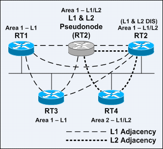
An IS-IS router may reside in a L1 area, in the L2 backbone, or both. L1/L2 routers connect L1 areas to the L2 backbone. An L1/L2 router will maintain a L1 routing table to route to ES and IS within its own area using System IDs, and a L2 prefix table to route to other areas. When the only L1/L2 router in an area failed, the area would be unreachable throughout the routing domain!

An L2 router is similar to an OSPF backbone router. The paths between the L2 and L1/L2 routers are called the backbone. All L2 and L1/L2 routers (the path of the backbone) must be contiguous – they cannot be separated by a L1 router somewhere in the middle.

An IS-IS router normally has 1 NET address. The limit is 3 NETs for conventional IS-IS; and 3 NETs per area for multiarea Integrated IS-IS. Configuring multiple NETs on routers is a useful technique for merging 2 domains or transitioning from one addressing scheme to another. If multiple NETs are configured on the same router, they all must have the same System ID. The default can be changed using the max-area-addresses router subcommand.
Note: The wording of area in this context is more appropriate being referred to as process.

Area Boundaries of OSPF and IS-IS

IS-IS area boundaries lie on links instead of routers as with OSPF. Each IS-IS router belongs to exactly one area. Neighboring routers are able to learn that they are in the same or different areas and negotiate the appropriate adjacencies – L1, L2, or both.

[Integrated] IS-IS has its own Protocol Data Units (PDUs) to transport information between ISs. Conventional IS-IS and Integrated IS-IS routing information is not carried within a network layer routed protocol (eg: CLNP) but is instead encapsulated directly within data link layer frames.

With OSPF, network design is constrained because OSPF is based on a central backbone area 0, with the restriction that all other areas must be physically or logically connected to backbone. In comparison, IS-IS has a hierarchy of L1, L1/L2, and L2 routers. IS-IS permits a more flexible approach upon extending the backbone. The backbone can be extended by simply adding additional L1/L2 or L2 routers, a much less-complex process than with OSPF.

OSPF generates many types of small LSAs; whereas IS-IS groups IS-IS updates and sends them in a single LSP. As the network complexity increases, flooding of IS-IS updates is not an issue. Since each packet must be routed though, and routing takes network resources, so more packets represent a larger impact on the network. Since IS-IS uses significantly fewer LSPs, more routers, at least 1000, can reside in a single area, making IS-IS more scalable than OSPF.

IS-IS and OSPF Routing Updates

IS-IS is also more efficient than OSPF in terms of CPU usages and processing routing updates. There are fewer LSPs (LSAs in OSPF terminology) to process. Besides that, the mechanism by which IS-IS installs and withdraws prefixes is less resource intensive as it uses NET addresses, which are already summarized.

The convergence time depends on various factors, eg: timers, number of nodes, and router type. Based on the default times, IS-IS detects a failure faster than OSPF; therefore faster convergence. IS-IS has more timers than OSPF for fine-tuning and achieve finer granularity. Convergence time can be decreased significantly by fine-tuning those timers.

L1/L2 routers should implement route summarization. Route summarization has many benefits. It saves CPU and memory resources since every router no longer responsible for the LSPs of the entire routing domain, and topology changes can be isolated to a small portion of the network instead of be propagating throughout the entire domain; therefore routers in other portions of the network can spend lesser time and resources for routing convergence upon topology changes.

Below lists the rules for implementing route summarization on IS-IS:
  • All L2 routers can summarize routes at the area boundary.
  • When an L1/L2 router is summarizing routes sent to an L2 router, all L1/L2 routers must summarize in the same way.
  • All L1 routers cannot summarize routes.

Older implementations of IS-IS use narrow metrics, which limits the maximum interface metric to 63 (6-bit) and the maximum total path metric to 1023 (10-bit); hence provides little space to distinguish between paths. Cisco IOS Software Release 12.0 and later support wide metrics, which allows a 24-bit interface metric and a 32-bit path metric. However, Cisco IOS uses narrow metrics by default. Mixing routers using narrow and wide metrics would increase complexities. The metric-style narrow, metric-style wide, and metric-style transition router subcommands instruct an IS-IS router to generate and accept old-style, new-style, and both styles of TLVs respectively.

Narrow- and wide-style metrics are not compatible with each other. Migration from narrow to wide metric is a 2-stage process using the transition keyword. The metric-style transition IS-IS router subcommand should first be configured on all routers that are using narrow metrics. Once the whole network support both old- and new-style TLVs, the wide-style metric can then be implemented using the metric-style wide IS-IS router subcommand on all routers.
The metric defines the cost to a destination. ISO 10589 defined the following 4 types of metrics:

Default Also referred to as cost. Every Integrated IS-IS router must support this metric. The default cost applied to the outgoing interface of a Cisco router interface is 10.
Delay An optional metric that reflects the transit delay.
Expense An optional metric that reflects the monetary expense of the network.
Error An optional metric that is based on the reliability of the path.
Note: Optional metrics are chosen before the default metric; however, Cisco supports only the default metric.

Another issue of the Cisco IS-IS implementation is that it does not scale the interface metric. All IS-IS interfaces have a default metric value of 10; however, this can be changed manually. If the default metric is not adjusted on each interface, the IS-IS metric becomes similar to the hop count metric of Routing Information Protocol (RIP).

Default IS-IS Path Metric Calculation

New ideas cannot be easily expressed as with OSPF, as they require the creation of a new LSA. The OSPF description schema is difficult to extend due to compatibility issues and it was developed exclusively for IPv4. IS-IS was designed with simplicity in mind, well-structured data formats, and can be easily extended through the Type, Length, and Value (TLV) mechanism. TLV triplets encode all IS-IS updates. This protocol-independence feature makes IS-IS easily extensible. IS-IS can easily grow to cover IPv6 (Integrated IS-ISv6) or any other new protocols, as extending IS-IS is simply creating new TLV triplets.

An organization might choose OSPF over IS-IS because OSPF is more optimized and was designed exclusively as an IP routing protocol. Besides that, it is relatively easy to find both networking equipments and personnel to implement and support an OSPF network infrastructure. Furthermore, OSPF documentation is much more readily available than IS-IS documentation.

Below summarizes the differences between OSPF and Integrated IS-IS:

OSPF
Integrated IS-IS
Area border inside routers (ABRs) Area border on links
Each link in only 1 area Each router in only 1 area
Complex to extend the backbone Simple to extend the backbone
Many small LSAs sent Fewer LSPs sent
Runs on top of IP Runs on top of data-link layer
Requires IP addresses Requires IP and CLNS addresses
Default metric is scaled by interface bandwidth Default metric is 10 for all interfaces
Not easy to extend Highly extensible with new TLV triplets
Equipments, personnel, and documentation more readily available Equipments, personnel, and documentation not as readily available


IS-IS and OSPF have more similarities than differences.
Both routing protocols have the following characteristics:
  • They are open standard link-state routing protocols that utilize the Dijkstra’s Shortest Path First (SPF) algorithm for their operations.
  • They support VLSM and 2-level hierarchical routing.
  • They have similar flooding mechanisms using link-state advertisements (LSAs), link-state aging timers, and link-state database synchronization to maintain the LSDB.
  • They are successful in the largest and most-demanding deployments – ISP networks.
  • They converge quickly upon network changes.

The development of IS-IS begun before OSPF development. Most of the development of the OSPF and IS-IS routing protocols was done concurrently. The cooperation and competition between the development groups produced 2 protocols that are very similar, yet one is better because of the other. The practical differences between the 2 protocols mainly deal with the issues of resources usage and customization.

Most debates of the merits of IS-IS and OSPF are colored by their mutual history – different groups with different cultures developed them.

IS-IS was originally developed by Digital Equipment Corporation (DEC) for DECnet Phase V. In 1987, the ANSI chose it to be the OSI IGP. At that time it could route only CLNP. IS-IS’s evolution was ad-hoc; whereas OSPF was more formal. Below is a brief history of IS-IS:
  • 1985 – Originally called DECnet Phase V Routing.
  • 1988 – Adopted by ISO and renamed as IS-IS.
  • 1990 – Publication of RFC 1142 – OSI IS-IS Intra-domain Routing Protocol.
  • 1990 – Publication of RFC 1195 – Use of OSI IS-IS for Routing in TCP/IP and Dual Environments.
  • 1991 – Cisco IOS Software starts supporting IS-IS.
  • 1995 – Internet service providers (ISPs) start adopting IS-IS.
  • 2000 – Publication of IETF draft – IS-IS Extensions for Traffic Engineering.
  • 2001 – Publication of IETF draft – IS-IS Extensions in Support of Generalized MPLS.
IETF – Internet Engineering Task Force

The ISO process is an international standards development process. ISO and many other groups did not approve TCP/IP due to its origin – the US Department of Defense (DoD) protocol. From the perspective of ISO, the development of IP was chaotic and imprecise, based on the famous maxim of “loose consensus and running code”. From the perspective of the early Internet engineers, the ISO process was slow, irritating, and disenfranchising.

In 1988, the US National Science Foundation Network (NSFnet) was created. The IGP used was based on an early draft of IS-IS. The extensions to IS-IS for handling IP were developed in 1988. The development of OSPF just began during this time; OSPF was loosely based on IS-IS.

OSPF Version 1 (OSPFv1) was published in 1989, conflicts ensued between the supporters of IS-IS and OSPF. Eventually the IETF supported both, but with the unofficial endorsement of the IETF and its continued favor of OSPF, OSPF which provide native IP support became more popular eventually.

During the mid-1990s, large ISPs selected IS-IS as their IGPs for 2 reasons – IS-IS support IP and CLNS (solved 2 problems at once), and OSPF was still considered immature at the time.