The characteristics of an OSPF area determine the types of routing information it will receive. The main purpose behind all types of stub areas is to inject a default route into an area so that the external (and summary) LSAs are not flooded into the area. Replacing multiple external routes with a single default route reduces the size of LSDBs and routing tables in the OSPF routers within the stub area, reduces the memory requirements for OSPF routers within the stub area, and the OSPF routers run fewer SPF calculations as they will receive lesser routing updates.
Below describes the possible OSPF area types and their characteristics:
| Standard area | Accepts Type-1 and Type-2 link info updates, Type-3 and Type-4 summary routes, and Type-5 external routes. |
| Backbone area or transit area | The central entity to which all other areas connect. All other areas connect to this area to exchange routing information. The OSPF backbone area has all the properties of an OSPF standard area. |
| Stubby area | Doesn’t accept external routes (Type-4 and Type-5 LSAs) from other autonomous systems (via route redistribution). The OSPF routers within a stubby area use the default route as indicated as 0.0.0.0 to route packets to networks outside the autonomous system. Stubby areas cannot contain ASBRs; however, the ABR may be an ASBR. |
| Totally Stubby area | A Cisco-proprietary feature that further minimizes routing information than stubby area by filtering Type-4 and Type-5 LSAs, and Type-3 Net-Summary-LSAs from other areas within the autonomous system. |
| Not-So-Stubby-Area (NSSA) | NSSA is defined in RFC 3101 as an addendum to the OSPF RFCs. The OSPF NSSA offers the benefits that are similar to the stubby area. However, NSSA allows ASBRs (by introducing the Type-7 NSSA-External-LSA), which against the rules of OSPF stub area. |
| Not-So-Stubby-Totally-Stubby Area | Combines the characteristics of totally stubby area and NSSA – does not accept Type-3, Type-4, and Type-5 LSAs; allows ASBRs. |
An OSPF area is qualified as a stubby or totally stubby area if it has the following characteristics:
i) There is a single exit point (ABR) from the area; or if there are multiple exit points, multiple ABRs inject default route into the stub area and suboptimal routing is acceptable – routing to other areas or autonomous systems can take a suboptimal path to reach the destination network by exiting the stub area via an exit point that is farther from the destination than other exit points.
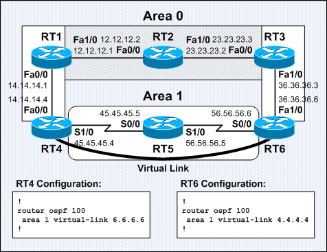
ii) The area is not needed as a transit area for virtual links.
iii) The area is not the backbone area.
iv) No ASBR is inside the stubby or totally stubby area.
v) All OSPF routers (internal routers and ABRs) within the stub area must be configured as stub routers for them to become neighbors and exchange routing information. The Hello packets exchanged between the routers will have the stub flag set – the E bit (ExternalRoutingCapability) of the Options field is set to 0.
Note: The ABR of a stub area generates a default route into the stub area regardless of whether it has a default route or received any external route from other ASBR resides in the standard area. A stub router selects the closest ABR as the gateway to reach networks outside the stub area.
OSPF Stubby Area
OSPF Stubby Area
Below shows the routing table and OSPF LSDB on RT4:
RT4#sh ip route

Gateway of last resort is 12.12.12.1 to network 0.0.0.0

     172.16.0.0/24 is subnetted, 1 subnets
O IA    172.16.1.0 [110/193] via 12.12.12.1, 00:00:24, Serial0/0
     10.0.0.0/30 is subnetted, 1 subnets
O IA    10.10.10.0 [110/192] via 12.12.12.1, 00:00:24, Serial0/0
     11.0.0.0/30 is subnetted, 1 subnets
O IA    11.11.11.0 [110/128] via 12.12.12.1, 00:00:30, Serial0/0
     12.0.0.0/30 is subnetted, 1 subnets
C       12.12.12.0 is directly connected, Serial0/0
O*IA 0.0.0.0/0 [110/65] via 12.12.12.1, 00:00:30, Serial0/0
RT4#
RT4#sh ip ospf database

            OSPF Router with ID (12.12.12.2) (Process ID 100)

--- output omitted ---

                Summary Net Link States (Area 2)

Link ID         ADV Router      Age         Seq#       Checksum
0.0.0.0         3.3.3.3         40          0x80000001 0x0057DA
10.10.10.0      3.3.3.3         26          0x80000001 0x00D6C0
11.11.11.0      3.3.3.3         36          0x80000001 0x0030A4
172.16.1.0      3.3.3.3         26          0x80000001 0x00CB28
RT4#
The ABR of a stubby or totally stubby area advertises a default route with a cost of 1 by default.
The
area {area-id} default-cost {cost} router subcommand changes the cost of the default route.
OSPF Totally Stubby Area
OSPF Totally Stubby Area
Below shows the routing table and OSPF LSDB on RT4, and the excerpt of show ip ospf on RT3:
RT4#sh ip route

Gateway of last resort is 12.12.12.1 to network 0.0.0.0

     12.0.0.0/30 is subnetted, 1 subnets
C       12.12.12.0 is directly connected, Serial0/0
O*IA 0.0.0.0/0 [110/65] via 12.12.12.1, 00:00:32, Serial0/0
RT4#
RT4#sh ip ospf database

            OSPF Router with ID (12.12.12.2) (Process ID 100)

--- output omitted ---

                Summary Net Link States (Area 2)

Link ID         ADV Router      Age         Seq#       Checksum
0.0.0.0         3.3.3.3         42          0x80000001 0x0057DA
RT4#
======================================================================
RT3#sh ip ospf
--- output omitted ---
    Area 2
        Number of interfaces in this area is 1
        It is a stub area, no summary LSA in this area
          generates stub default route with cost 1
--- output omitted ---
RT3#
RT4 is configured with the
area {area-id} stub command without the
no-summary keyword. The
no-summary keyword only required to be configured on the ABR of a totally stubby area to stop the ABR from propagating summary LSAs into the totally stubby area.
OSPF Not-So-Stubby-Area (NSSA)
OSPF Not-So-Stubby-Area (NSSA) is defined in
RFC 3101 – The OSPF Not-So-Stubby Area (NSSA) Option as an addendum to the official OSPF Request for Comments (RFC). It is a non-proprietary extension upon the OSPF stub area feature that allows ASBRs in a stub area and therefore allows the injection of external routes into the stub area in a limited fashion. The NSSA retains the main feature of stub areas – the NSSA ABR generates a default route into the NSSA instead of external routes originated from other ASBRs.
An ASBR within an NSSA originates Type-7 NSSA-External-LSA upon route redistribution. All fields of the NSSA-External-LSA and AS-External-LSA are identical except the Forward Address field. AS-External-LSAs are flooded throughout an OSPF routing domain; while NSSA-External-LSAs are flooded only within the NSSA in which it was originated. The
show ip ospf database nssa-external EXEC command displays NSSA-External-LSAs.
When an NSSA ASBR generates a Type-7 NSSA-External-LSA, the
NSSA ABR with the highest Router ID among the NSSA ABRs (when there are multiple NSSA ABRs) translates the Type-7 LSA to a Type-5 LSA and propagates it throughout the OSPF routing domain.
Type-7 NSSA-External-LSAs are denoted as O N2 or O N1 in the IP routing table. The metrics of N1 and N2 are calculated as like E1 Type-1 and E2 Type-2 external routes respectively.
The
area area-id nssa [default-information-originate [metric metric] [metric-type metric-type]] [no-redistribution] [no-summary] OSPF router subcommand is used instead of the
area area-id stub OSPF router subcommand to configure an NSSA OSPF router. All OSPF routers (internal routers and ABRs) within an NSSA must be configured as NSSA routers for them to become neighbors and exchange routing information. The Hello packets exchanged between the routers will have the NSSA flag (the N bit in the Options field) set to 1.
The
default-information-originate keyword generates a Type-7 default route into an NSSA. This keyword takes effect only on an NSSA ASBR or NSSA ABR. An NSSA ASBR can generate a default route only when it has a default route in its routing table; while an NSSA ABR can generate a default route with or without a default route in its routing table.
The
no-summary keyword of the
area {area-id} nssa OSPF router subcommand prevents summary routes from being advertised into an NSSA – it becomes a Totally Stubby NSSA or Not-So-Stubby-Totally-Stubby area. This keyword takes effect only on an NSSA ABR. A single default route would replace both external and summary routes into an NSSA.
Note: When
no-summary is configured, the
default-information-originate keyword is not required for the ABR on a totally stubby NSSA to generate a default route into the area.
The
no-redistribution keyword is used in situations where there is no need to redistribute external routes into an NSSA as Type-7 LSAs, eg: when an NSSA ASBR is also an NSSA ABR.
An ABR in an NSSA never originate Type-4 ASBR-Summary-LSA for the ASBR in the NSSA, as Type-7 NSSA-External-LSA never flooded beyond the border of the NSSA.
The totally stubby and No-So-Stubby-Totally-Stubby configurations are Cisco-proprietary features. Type-3 Network-Summary-LSAs (from other areas) are not flooded into both types of stub areas.
Routers in stub area can only establish adjacencies with routers in stub or totally stubby area; while routers in NSSA can only establish adjacencies with the routers in NSSA or totally NSSA.
OSPF Not-So-Stubby-Area (NSSA)
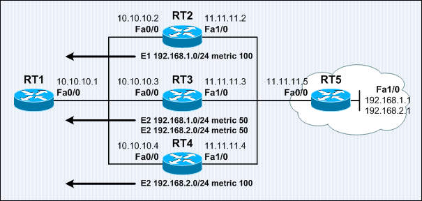
Below shows the routing table and OSPF LSDB on RT1:
RT1#sh ip route

Gateway of last resort is 10.10.10.2 to network 0.0.0.0

     20.0.0.0/30 is subnetted, 1 subnets
C       20.20.20.0 is directly connected, Serial0/0
     10.0.0.0/30 is subnetted, 1 subnets
C       10.10.10.0 is directly connected, Serial0/1
     11.0.0.0/30 is subnetted, 1 subnets
O IA    11.11.11.0 [110/128] via 10.10.10.2, 00:00:56, Serial0/1
S    192.168.1.0/24 [1/0] via 20.20.20.1
O*N2 0.0.0.0/0 [110/1] via 10.10.10.2, 00:00:57, Serial0/1
RT1#
RT1#sh ip ospf database

            OSPF Router with ID (1.1.1.1) (Process ID 100)

                Router Link States (Area 1)

Link ID         ADV Router      Age         Seq#       Checksum Link count
1.1.1.1         1.1.1.1         67          0x80000002 0x006BE5 2
2.2.2.2         2.2.2.2         69          0x80000001 0x00103C 2

                Summary Net Link States (Area 1)

Link ID         ADV Router      Age         Seq#       Checksum
11.11.11.0      2.2.2.2         64          0x80000001 0x00D5FA

                Type-7 AS External Link States (Area 1)

Link ID         ADV Router      Age         Seq#       Checksum Tag
0.0.0.0         2.2.2.2         69          0x80000001 0x00D0D8 0
192.168.1.0     1.1.1.1         68          0x80000001 0x00EF19 0
RT1#
Below shows the routing table and OSPF LSDB on RT2 and RT3:
RT2#sh ip route

Gateway of last resort is not set

     10.0.0.0/30 is subnetted, 1 subnets
C       10.10.10.0 is directly connected, Serial0/0
     11.0.0.0/30 is subnetted, 1 subnets
C       11.11.11.0 is directly connected, Serial0/1
O N2 192.168.1.0/24 [110/20] via 10.10.10.1, 00:00:55, Serial0/0
RT2#
RT2#sh ip ospf
--- output omitted ---
    Area 1
        It is a NSSA area
        Perform type-7/type-5 LSA translation
        generates NSSA default route with cost 1
--- output omitted ---
RT2#sh ip ospf database
--- output omitted ---

                Type-7 AS External Link States (Area 1)

Link ID         ADV Router      Age         Seq#       Checksum Tag
0.0.0.0         2.2.2.2         70          0x80000001 0x00D0D8 0
192.168.1.0     1.1.1.1         71          0x80000001 0x00EF19 0

                Type-5 AS External Link States

Link ID         ADV Router      Age         Seq#       Checksum Tag
192.168.1.0     2.2.2.2         64          0x80000001 0x0066A8 0
RT2#
======================================================================
RT3#sh ip route

Gateway of last resort is not set

     10.0.0.0/30 is subnetted, 1 subnets
O IA    10.10.10.0 [110/128] via 11.11.11.1, 00:00:57, Serial0/0
     11.0.0.0/30 is subnetted, 1 subnets
C       11.11.11.0 is directly connected, Serial0/0
O E2 192.168.1.0/24 [110/20] via 11.11.11.1, 00:00:57, Serial0/0
RT3#sh ip ospf database

            OSPF Router with ID (3.3.3.3) (Process ID 100)

                Router Link States (Area 0)

Link ID         ADV Router      Age         Seq#       Checksum Link count
2.2.2.2         2.2.2.2         73          0x80000001 0x000144 2
3.3.3.3         3.3.3.3         67          0x80000002 0x0095AC 2

                Summary Net Link States (Area 0)

Link ID         ADV Router      Age         Seq#       Checksum
10.10.10.0      2.2.2.2         68          0x80000001 0x005485

                Type-5 AS External Link States

Link ID         ADV Router      Age         Seq#       Checksum Tag
192.168.1.0     2.2.2.2         66          0x80000001 0x0066A8 0
RT3#
OSPF Totally Stubby NSSA
OSPF Totally Stubby NSSA
Below shows the routing table and OSPF LSDB on RT1:
RT1#sh ip route

Gateway of last resort is 10.10.10.2 to network 0.0.0.0

     20.0.0.0/30 is subnetted, 1 subnets
C       20.20.20.0 is directly connected, Serial0/0
     10.0.0.0/30 is subnetted, 1 subnets
C       10.10.10.0 is directly connected, Serial0/1
S    192.168.1.0/24 [1/0] via 20.20.20.1
O*IA 0.0.0.0/0 [110/65] via 10.10.10.2, 00:00:10, Serial0/1
RT1#
RT1#sh ip ospf database

            OSPF Router with ID (1.1.1.1) (Process ID 100)

                Router Link States (Area 1)

Link ID         ADV Router      Age         Seq#       Checksum Link count
1.1.1.1         1.1.1.1         24          0x80000002 0x006BE5 2
2.2.2.2         2.2.2.2         28          0x80000001 0x00103C 2

                Summary Net Link States (Area 1)

Link ID         ADV Router      Age         Seq#       Checksum
0.0.0.0         2.2.2.2         28          0x80000001 0x00FC31

                Type-7 AS External Link States (Area 1)

Link ID         ADV Router      Age         Seq#       Checksum Tag
192.168.1.0     1.1.1.1         26          0x80000001 0x00EF19 0
RT1#
OSPF Stubby Area Types