Showing posts with label eigrp. Show all posts

Sunday, December 4, 2011

EIGRP Stub Routing

In hub-and-spoke environments, spoke routers (branch routers) often do not need to maintain complete routing tables of the network, as the paths to other portions of the network are always through the hub routers (head quarter routers). Additionally, the massive query-reply processes between the hub and spoke routers upon a loss route would affect the stability of the network.

A typical connection between a hub router and a spoke router has much less bandwidth than a connection in the network core. Therefore attempting to use such connections as transit paths would typically results in excessive congestion. EIGRP stub routing can prevent this problem by restricting the spoke router from advertising the routes from a hub router to another hub router. As a result, the hub routers would not notice there is an alternative path through the spoke router. However, stub routing is unable to stop the hub router from advertising routes to spoke router. Manual summarization is required on the hub to advertise only a default route to the spokes.
Note: A stub router would not advertise routes received from a neighbor to another neighbor.

Without stub routing implemented on dual-homed spoke routers, route filtering configuration is required on the spoke routers to prevent them from appearing as transit paths to the hub routers.

When the remote sites are not acting as a transit sites between the regional sites, the regional routers (hubs) should be configured to advertise only a default route to the remote routers. The remote routers (spokes) should be configured to advertise only their directly connected stub networks back to the regional routers to reduce the complexity of EIGRP convergence (the query-reply process) and the sizes of the EIGRP topology table and IP routing table.

EIGRP stub routing an efficient method for limiting the query range, therefore conserves bandwidth due to unnecessary queries, prevents SIA events, and improves network stability.

An EIGRP stub router would inform its stub status to upstream routers via the Hello packets. Any neighboring upstream router that receives such Hello packets will not query the stub router for lost routes, as the stub router has no downstream EIGRP neighbors and hence would not have alternative paths for a lost route. The upstream routers which connected to the stub router would answer any query on behalf of the stub router, which results in improved convergence time.

The eigrp stub [receive-only | connected , static , summary , redistributed] router subcommand configures an EIGRP router as an EIGRP stub router. An EIGRP stub router would advertise its connected and summary routes to other neighboring routers by default. Below describes the optional keywords that can be used to modify this behavior:

Keyword Description
receive-only Restricts an EIGRP stub router from advertising any route to other routers. This option cannot be used with any other option as it prevents the advertisement of any type of route, which is not really useful; the other options can be configured in any combination. Use this option when the stub router has only a single interface.
connected Allows an EIGRP stub router to advertise its connected routes. The network statement is required to include the connected interfaces into the EIGRP routing process. The redistribute connected router subcommand can also be used to redistribute connected subnets into the EIGRP routing process. This option is enabled by default and is the most widely used option.
static Allows an EIGRP stub router to advertise its static routes. The redistribute static router subcommand is required to redistribute static routes.
summary Allows an EIGRP stub router to advertise its summary routes. Summary routes can be configured manually with the ip summary-address eigrp interface subcommand or automatically with the auto-summary router subcommand. This option is enabled by default.
redistributed Allows an EIGRP stub router to advertise external EIGRP routes learnt from other routing protocols or other EIGRP autonomous systems.
Note: Configuring EIGRP stub routing would teardown existing EIGRP neighbor relationships!

By implementing EIGRP stub routing on BR1 and BR2, HQ1 and HQ2 would notice both branch routers as stub routers and will suppress the queries to these neighbors. HQ1 and HQ2 will no longer query BR1 and BR2 when the successor to 172.16.1.0/24 is lost; they will send update packets to BR1 and BR2 instead. However, BR1 and BR2 will still query HQ1 and HQ2 as they lost both the successor and feasible successor to 172.16.1.0/24.
HQ1#sh ip eigrp neighbors detail
IP-EIGRP neighbors for process 100
H   Address                 Interface       Hold Uptime   SRTT   RTO  Q  Seq
                                            (sec)         (ms)       Cnt Num
2   10.10.10.10             Se1/1             14 00:02:28    1  4500  0  22
   Version 12.3/1.2, Retrans: 2, Retries: 0
   Stub Peer Advertising ( CONNECTED ) Routes
   Suppressing queries
1   10.10.10.6              Se1/0             13 00:02:29    1  4500  0  22
   Version 12.3/1.2, Retrans: 2, Retries: 0
   Stub Peer Advertising ( CONNECTED ) Routes
   Suppressing queries
0   10.10.10.2              Fa0/0             12 00:02:30  424  3816  0  25
   Version 12.3/1.2, Retrans: 1, Retries: 0
HQ1#

EIGRP Query-Reply Process and Stuck-in-Active Routes

When an EIGRP router loses a route that does not have a FS in its topology table, it will look for an alternative path to the destination. The route is now considered active. A route is considered passive when a router is not performing computation for the particular route. Re-computing an active route involves sending query packets to all neighbors on interfaces other than the one used for the previous successor (due to the split horizon rule), inquiring whether they have a route to the particular destination. If a neighbor has an alternative route, it will answer the query with the path in a reply packet and does not further propagate the query packet. If a neighbor does not have an alternative path, it will continue to query its own neighbors for an alternative path. The queries would be propagated through the network and create an expanding tree of queries.

When a router replies a query, it stops spreading of the query through that branch of the network. However, the query can still spread through other portions of the network as other routers attempt to find alternative paths which might not exist.

Due to the nature of the reliable multicast approach implemented by EIGRP, a reply must be received for each query generated when searching for alternative paths for a lost route. When a route enters the active state and queries are initiated, the only way the route can come out of the active state and transitions to passive state is after the router received a reply for every query generated! Besides that, every query and reply is acknowledged using an ACK message!

For each neighbor to whom a query is sent, an EIGRP router will set a reply status flag (r) to keep track of all outstanding queries that are waiting for replies. The DUAL computation is completed when the router has received a reply for every query sent out earlier.

By default, if an EIGRP router does not receive a reply to for each outstanding query within 3 minutes (the default Active timer value), the route will enter into the Stuck-in-Active (SIA) state. When a route is in the SIA state, the router will reset the neighbor relationships for neighbors that failed to reply, and cause the router to go active on all routes known through the neighbors and re-advertise all its known routes to the neighbors. Query scoping, which limits the scope of query propagation through a network – query range, helps to reduce the occurrences of SIA. Keeping the query packets close to the source reduces the chance that a failure in a part of the network to involve routers in other parts of the network in the query-reply convergence process.

The best methods for limiting the scope of query range and building scalable EIGRP networks:
i) Configure route summarization on the outbound interfaces of the appropriate routers.
ii) Configure the remote routers as EIGRP stub routers.

Other methods used for limiting query range include route filtering and interface packet filtering. Ex: When specific EIGRP routing updates to a router are filtered, upon the router receives a query about a filtered network, the router would reply and indicate that the network is unreachable and does not further propagate the query to other neighbors.

The timers active-time [time-limit | disabled] EIGRP router subcommand changes the active-state time limit in minutes. The default value which is 3 minutes – timers active-time 3 will not be shown in the router configuration files. The timers active-time command is equivalent to the timers active-time disabled command. With the active timer disabled, SIA route which does not receive a reply within 3 minutes would not cause the reset of the neighborship between the querying and queried routers.

The eigrp log-neighbor-changes router subcommand enables the logging of neighbor adjacency events monitors the stability of the routing system and detects SIA-related problems.
Note: This command is enabled by default.
Note: The show ip eigrp sia-event hidden EXEC command displays the SIA events.

An erroneous approach which is often used to decrease the chance of occurrence of a SIA route is implementing multiple EIGRP ASs to somewhat simulate OSPF areas in order to bound the query range, with mutual redistribution between the different ASs. However, this approach will not achieve the intended results. When a query reaches the edge of an AS, where routes are redistributed into another AS, the original query is first answered, followed by the edge router initiates a new query in the other AS. As a result, the query process has not been stopped; the querying process continues into other AS, and the route can eventually enter into SIA.

Another misconception about AS boundaries is implementing multiple ASs to protect one AS from route flapping in another AS. If routes are being redistributed between ASs, route transitions occur in an AS will be detected in the other ASs.

The EIGRP Query-Reply Process on Redundant Topology

The figure above is used for the discussion of the EIGRP Query-Reply process upon a lost route on redundant topology. The convergence process is considered complex even with only 2 head quarter routers and 2 branch routers. In networks with hundreds of branch routers, the process would become even more complex and can cause severe problems.

HQ1 advertises 172.16.1.0/24 to all other routers. The successor path for HQ2 to reach the network is via the Fast Ethernet link to HQ1. The successor paths for branch routers (BR1 and BR2) to reach the network are via their serial links to HQ1. Additionally, they have also learnt the feasible successor path through HQ2.

Assume that the EIGRP metrics for Fast Ethernet and Serial are 100 and 1000 respectively.

Below shows the EIGRP topology table for BR1 and BR2 for network 172.16.1.0/24. BR1 and BR2 have determined that the path to HQ1 is the successor while the path to HQ2 is the feasible successor (the AD is 200 through HQ2, which is less than the FD through HQ1) for the network.

Neighbor Feasible Distance Advertised Distance
HQ1 1100 100
HQ2 1200 200

Below shows the EIGRP topology table for HQ2 for network 172.16.1.0/24. HQ2 does not have a FS, as all paths through the branch routers have an AD greater than the FD through HQ1.

Neighbor Feasible Distance Advertised Distance
HQ1 200 100
BR1 2100 1100
BR2 2100 1100

At a particular time, HQ1 lost the route to 172.16.1.0/24 due to a network device failure. It sends a query to HQ2, BR1, and BR2 to seek for a feasible successor as it does not have any. When the branch routers receive the query, they automatically install the feasible successor path through HQ2 into their routing tables and respond to HQ1 with their new successor through HQ2. They also remove the unreachable path through HQ1 from their routing tables and install the path through HQ2 into their routing tables.

Now HQ1 has received the responses for 2 out of its 3 queries, but it is still waiting for the response from HQ2. When HQ2 receives the query from HQ1 for 172.16.1.0/24, it propagates the query to BR1 and BR2, as it does not have a FS but knows that a path exists through each branch router to reach 172.16.1.0/24.

BR1 and BR2 receive the query from HQ2 and check their topology tables for alternative paths. However, both branch routers do not have another path at the moment, as HQ1 has just informed that it has lost the path to this network. As the branch routers do not have an answer to the query from HQ2, they create a query and send it to all neighbors except the neighbor that they received the query from (due to split horizon). In this case, the branch routers send the query to HQ1.

HQ1 would reply to BR1 and BR2 that the route has an infinite metric and is unreachable. Once BR1 and BR2 receive the reply, the edge of the network is reached and the edge routers do not have any more neighbors to query. BR1 and BR2 would reply back to HQ2 and eventually HQ2 would reply back to HQ1.
Note: The longest query range in this sample network is HQ1 > HQ2 > BR1, BR2 > HQ1.

Below summarizes the events of the Query-Reply process in this scenario:
1) HQ1 sends queries to HQ2, BR1, and BR2.
2) BR1 and BR2 reply to HQ1 with their feasible successor paths via HQ2.
3) HQ2 propagates the query from HQ1 to BR1 and BR2 as it does not have a feasible successor path.
4) BR1 and BR2 propagate the query from HQ2 to HQ1.
5) HQ1 replies to BR1 and BR2 that it does not have a feasible successor path.
6) BR1 and BR2 reply back to HQ2.
7) HQ2 replies back to HQ1.

This scenario shows that in a network with redundant links between the head quarter and branch offices, not only the branch routers are required to respond to queries from the head quarter, but they also continue the search for a successor by propagated the queries back to the head quarter – HQ2 in this case. The Query-Reply packets which may traverse from the head quarter to the branch offices and back to the head quarter is often overlooked by network architects.

Route summarization can limit the query range by limiting the knowledge of a router regarding the subnets in a network. When a subnet is down, queries will only be propagated to as far as the routers that receive the summary route and do not have knowledge about the specific subnet, as a router propagates the query about a network only if it has an exact match in the routing table.

Route Summarization Limits the Scope of EIGRP Query Range

The figure above shows a sample scenario in which RT2 advertises a summary route of 172.16.0.0/16 to RT3. When the network 172.16.1.0/16 is down, RT3 would receive a query from RT2 as propagated from RT1. As RT3 has received only a summary route and the specific queried network is not in its routing table, it would reply with a “Network 172.16.1.0/24 is unreachable” message with an infinite metric of 4294967295 and does not further propagate the query to RT4.

However, RT2 would send a query for the summary route 172.16.0.0/16 to RT3 and the query will be propagated to RT4 as the only component subnet 172.16.1.0/24 is unreachable while it requires at least one valid component subnet for the summary route to remain in its routing table. In production environments, RT1 should have multiple directly connected subnets in the 172.16.0.0/16 major network and hence this additionally query-reply process will never occur.
Note: The FD of a summary route is same as the FD to the lowest-metric component subnet. If RT2 have different metric to the component subnets as advertised from RT1, it would send out a query to RT3 and the query will be propagated to RT4 when the lowest-metric component subnet which determines the metric for the summary route is unreachable, as it would like to query for any metric that is lower or better than its next lowest-metric component subnet that determines the metric for the 172.16.0.0/16 summary route.

Route summarization can be implemented on the network as shown in Figure 6-10 to reduce the convergence traffic (queries and replies) on the redundant topology. The ip summary-address eigrp 100 172.16.0.0 255.255.0.0 interface subcommand which configured on the outbound interfaces of the head quarter routers allows HQ1 and HQ2 to advertise the 172.16.0.0/16 summary route instead of the specific route to the branch routers – BR1 and BR2. Eventually, BR1 and BR2 will not propagate the query for 172.16.1.0/24 back to HQ1, but will reply to a query for 172.16.1.0/24 with the “network is unreachable” message instead.

EIGRP Authentication

EIGRP neighbor authentication (also known as neighbor router authentication or route authentication) configures EIGRP routers to only participate in routing domain based on predefined passwords for preventing an EIGRP router from receiving unauthorized or fraudulent routing updates from unknown sources. An EIGRP router configured with neighbor authentication will authenticate the source of all types of EIGRP packets except ACK packets.

Cisco IOS supports the following types of authentication for common routing protocols:

Simple password authentication Also known as plain text authentication. Sends the authentication key over across the network and therefore vulnerable to passive attacks. Supported by RIPv2, OSPF, and IS-IS.
Message Digest 5 (MD5) authentication Sends a message digest or hash instead of the authentication key. The message digest or hash is appended to routing update packets. Supported by RIPv2, EIGRP, OSPF, and BGP.
Note: EIGRP only supports the MD5 authentication method.

Authentication keys can be managed using key chains. A key defined within a key chain can specify a time interval for which the key will be activated, referred to as the lifetime of the key. Routing update packets will be sent with the valid or activated key based on the lifetime of a key. The 1st valid key that is encountered in the series of keys with the lowest to highest key ID number will be used at a time regardless of the number of valid keys. The key ID numbers do not need to be consecutive. However, at least 1 key must be defined within a key chain.

EIGRP MD5 Authentication Configuration

The accept-lifetime {start-time} {infinite | end-time | duration secs} and the send-lifetime {start-time} {infinite | end-time | duration secs} key chain key configuration subcommands are optional for specifying the time period in which a particular key will be accepted for received packets and used for sending packets respectively. When intended to set lifetimes on keys, ensure that the time of network devices are synchronized via NTP.

Thursday, December 1, 2011

EIGRP and WAN Links

EIGRP operates efficiently in WAN environments. EIGRP is scalable on both point-to-point links and NBMA multipoint and point-to-point links, eg: X.25, Frame Relay, and ATM. Due to the inherent differences of the operational characteristics, the default configuration of WAN connections might not be optimal. A solid understanding of EIGRP operation and the knowledge of link speeds can produce an efficient, reliable, scalable router configuration.

By default, EIGRP is allowed to use up to 50% of the bandwidth of an interface or subinterface. EIGRP uses the default bandwidth of the link, or the bandwidth set by the bandwidth interface subcommand when calculating how much bandwidth to use.

The EIGRP pacing feature allows the fine-tuning of the bandwidth usage of a link for transmitting EIGRP traffic. The ip bandwidth-percent eigrp {as-num} {percent} interface subcommand adjusts the EIGRP link utilization for an [sub]interface based on the interface’s bandwidth value. The percent value is ranging from 1 to 999999. A percent value greater than 100 is reasonable if the bandwidth is configured artificially low for some routing policy reasons or to accommodate an oversubscribed multipoint Frame Relay interface.
Ex: A 512kbps interface is configured with a logical bandwidth of 56kbps. 200% is configured when 112kbps (2 x 56) is allocated for EIGRP traffic.
Note: Make sure that the physical link is provisioned to handle the configured capacity.

Cisco IOS treats Frame Relay point-to-point subinterfaces in the same manner as serial interfaces in terms of bandwidth. It assumes both of them are operating at full T1 link speed. However, only fractional T1 speeds are available in most implementations. Therefore, always remember to set the bandwidth to match the provisioned CIR when configuring these subinterfaces.

When configuring Frame Relay multipoint interfaces, remember that the bandwidth is shared equally by all neighbors – EIGRP uses the bandwidth of the physical interface divided by the number of Frame Relay neighbors connected on the physical interface to obtain the bandwidth attributed to each neighbor. EIGRP configuration should be fine-tuned to reflect the appropriate percentage of the actual available bandwidth for the link.

Figure 1: Frame Relay Multipoint with all VCs Share the Bandwidth Evenly

Figure 1 shows a Frame Relay network where RT1 has a Frame Relay multipoint interface and all VCs share the bandwidth evenly. The RT1 Frame Relay multipoint interface is configured for a bandwidth of 168kbps (3 x 56kbps CIR).

The sample network in Figure 2 have the same configuration as for Figure 1, where one of the circuits has been provisioned for a 56kbps CIR, and the other circuits have a higher CIR. RT1 Frame Relay multipoint interface is configured for a bandwidth that represents the lowest CIR multiplied by the number of circuits – 56 x 3 = 168. This approach might not fully utilize the higher-speed circuits, but it protects the circuit with the lowest CIR from being overwhelmed.

Figure 2: Frame Relay Multipoint with all VCs Have Different CIRs

Figure 3: Hybrid Frame Relay Network with Multipoint and Point-to-Point

Figure 3 shows a hybrid Frame Relay network, where there is 1 low-speed circuit and other VCs provisioned for a higher CIR. The lowest CIR VC is configured as point-to-point with the bandwidth equals to CIR; the higher CIR VCs are configured as multipoint with combined CIRs.

Figure 4: Frame Relay Hub-and-Spoke Network

Figure 4 shows a common oversubscribed Frame Relay hub-and-spoke topology with 10 VCs to the remote sites (only 3 remote sites are shown in the figure). The circuits are provisioned with 56kbps CIR, but there is insufficient bandwidth at RT1 interface to support the allocation.

All VCs are treated equally and are configured for about 1/10 (25kbps) of the RT1 link speed, and EIGRP link utilization is increased to 50% of the actual point-to-point VC capacity (56kbps). By default, EIGRP uses 50% of the bandwidth of a circuit. EIGRP configuration should reflect the correct percentage of the actual available bandwidth on the line. Therefore, each subinterface has the EIGRP allocation percentage raised up to 110% (~28kbps) of the specified bandwidth in order to ensure enough bandwidth to deliver EIGRP packets through the Frame Relay network. This configuration restores the 50-50 ratio when the bandwidth value was set artificially low for some reasons, eg: manipulation of the routing metric or to accommodate an oversubscribed multipoint Frame Relay configuration on the hub router interface.

The ip bandwidth-percent command relies upon the value set by the bandwidth command.

EIGRP can further conserve WAN bandwidth by suppressing ACKs. An ACK will not be sent if a unicast data packet is ready for transmission, as the ACK field in any RTP unicast packet is sufficient to acknowledge the EIGRP packets received from a neighboring router, therefore the ACK packet will be suppressed to conserve bandwidth. This is an essential feature for point-to-point links and NBMA networks, as on those environments, all data packets are sent as unicasts, and hence can carry an acknowledgement themselves (also known as piggyback ACK). In those environments, there is no need for ACK packets.

The show ip eigrp interfaces detail [intf-type intf-num] EXEC command shows the numbers of ACK packets suppressed for a particular interface.
Router#sh ip eigrp interfaces detail s0/0
IP-EIGRP interfaces for process 100

                        Xmit Queue   Mean   Pacing Time   Multicast    Pending
Interface        Peers  Un/Reliable  SRTT   Un/Reliable   Flow Timer   Routes
Se0/0              0        0/0         0       0/10           0           0
  Hello interval is 5 sec
  Next xmit serial 
  Un/reliable mcasts: 0/0  Un/reliable ucasts: 0/0
  Mcast exceptions: 0  CR packets: 0  ACKs suppressed: 0
  Retransmissions sent: 0  Out-of-sequence rcvd: 0
  Authentication mode is not set
Router#

EIGRP Load Balancing

Load balancing is a router capability to distribute traffic over multiple network paths that have the same metric to a destination network.

Good load balancing algorithms utilize both line speed and reliability information. Load balancing increases the utilization of network links and eventually increases the effective bandwidth and throughput.

Cisco IOS perform load balancing across of 4 equal-cost paths by default. The maximum-paths {max-paths-num} router subcommand defines the number of same metric parallel paths to a same destination network that can be added to the routing table and perform load balancing across the links in round-robin basis. Set max-paths-num to 1 to disable load balancing.
Note: When packets are process-switched, load balancing occurs on a per-packet basis. When packets are fast-switched, load balancing occurs on a per-destination basis.

Note: Load balancing is performed only on traffic that passes through a router, not traffic that originated by the router. Hence when testing load balancing, do not issue ping and observe the results from the router that connects to the same metric parallel paths, as the locally generated ping packets are process-switched rather than fast-switched and might produce confusing results.

EIGRP and IGRP are able to perform load balancing across multiple routes with different metrics – unequal-cost load balancing. The variance {multiplier} router subcommand defines the variance value (between 1 and 128) which defines routes with metric value less than or equal to lowest metric x variance multiplier are considered equal and will be used for load balancing. The default is 1, which means equal cost load balancing. Ex: With a lowest metric of 100 and variance of 2, all routes with a metric ≤ 200 are considered equal.


Only paths that meet the feasibility condition can be used for unequal-cost load balancing. A path or route can only be considered as a feasible successor when:
i) The advertised distance from the next router (the feasible distance of the next router) must be less than the lowest-metric (feasible distance) of the local router to the destination. This means that the next router in the path must be closer to the destination than the local router in order to prevent routing loops.
ii) The feasible distance through the next router must be less than or equal to the lowest metric (feasible distance) of the local router multiplied with the variance multiplier.
* If a path isn’t a feasible successor, it isn’t used in load balancing, even if variance is configured!

Network Setup for EIGRP Load Balancing

Below shows that after changing the variance multiplier to 10 on RT1, the path to 172.16.1.0/24 via RT4 is not considered feasible, even the FD via RT4 – 309760 is less than lowest metric multiplied with the variance multiplier – 332800; because the AD of RT4 – 284160, is not less than the FD of RT1 to 172.16.1.0/24 – 33280.
RT1#sh ip route

Gateway of last resort is not set

     172.16.0.0/24 is subnetted, 1 subnets
D       172.16.1.0 [90/33280] via 10.10.10.2, 00:01:00, FastEthernet0/0
     10.0.0.0/30 is subnetted, 6 subnets
C       10.10.10.8 is directly connected, Ethernet1/0
D       10.10.10.12 [90/33280] via 10.10.10.2, 00:01:00, FastEthernet0/0
C       10.10.10.0 is directly connected, FastEthernet0/0
D       10.10.10.4 [90/30720] via 10.10.10.2, 00:01:00, FastEthernet0/0
C       10.10.10.16 is directly connected, Ethernet1/1
D       10.10.10.20 [90/286720] via 10.10.10.2, 00:01:00, FastEthernet0/0
RT1#
RT1#sh ip eigrp topology all-links | b 172.16.1.0
P 172.16.1.0/24, 1 successors, FD is 33280, serno 10
        via 10.10.10.2 (33280/30720), FastEthernet0/0
        via 10.10.10.18 (309760/284160), Ethernet1/1
        via 10.10.10.10 (286720/30720), Ethernet1/0
RT1#
RT1#conf t
Enter configuration commands, one per line.  End with CNTL/Z.
RT1(config)#router eigrp 100
RT1(config-router)#variance 10
RT1(config-router)#^Z
RT1#sh ip route

Gateway of last resort is not set

     172.16.0.0/24 is subnetted, 1 subnets
D       172.16.1.0 [90/33280] via 10.10.10.2, 00:00:10, FastEthernet0/0
                   [90/286720] via 10.10.10.10, 00:00:10, Ethernet1/0
     10.0.0.0/30 is subnetted, 6 subnets
C       10.10.10.8 is directly connected, Ethernet1/0
D       10.10.10.12 [90/33280] via 10.10.10.2, 00:00:10, FastEthernet0/0
                    [90/284160] via 10.10.10.10, 00:00:10, Ethernet1/0
C       10.10.10.0 is directly connected, FastEthernet0/0
D       10.10.10.4 [90/30720] via 10.10.10.2, 00:00:10, FastEthernet0/0
C       10.10.10.16 is directly connected, Ethernet1/1
D       10.10.10.20 [90/286720] via 10.10.10.2, 00:00:10, FastEthernet0/0
                    [90/307200] via 10.10.10.18, 00:00:10, Ethernet1/1
                    [90/309760] via 10.10.10.10, 00:00:10, Ethernet1/0
RT1#
Tips: Always write out the FD and AD of all routes in a network diagram before deciding whether the variance command allows the use of all paths.

The traffic-share {balanced | min across-interfaces} router subcommand controls how traffic is being distributed among routes when multiple different costs routes exist for the same destination network – traffic sharing. With the balanced keyword, the router distributes traffic proportionately to the ratios of the metrics associated with the different routes. With the min across-interfaces keyword, the router uses only routes that have minimum costs – all routes that are feasible and within the variance are maintained in the routing table, but only those with the minimum cost will used for forwarding packets.

Tuesday, November 29, 2011

EIGRP Route Summarization

Summarizing routes automatically up to the major network boundary is an EIGRP feature that inherited from traditional distance vector routing protocols (the predecessor of EIGRP is IGRP, a DV routing protocol). Traditional DV routing protocols are classful routing protocols that must summarize at the network boundaries. They have no idea regarding the subnet masks for non-directly connected networks, as subnet masks are not being exchanged in routing updates.

EIGRP performs autosummarization by default. This feature can be disabled and must be disabled for discontiguous networks. Additionally, EIGRP summary routes within a network can be configured on any bit boundary as long as a more-specific route exists in the routing table. EIGRP supports summarization at any router; unlike OSPF, which must be performed on an Area Border Router (ABR) or Autonomous System Border Router (ASBR).

When route summarization is configured on an interface, a summary route destined to the Null0 interface, a directly connected, software-based interface as the next-hop interface will be added to the routing table. The Null0 interface is often used to prevent routing loop in a network. Ex: If the summarizing router receives a packet to an unknown subnet that is part of the summarized range, the packet matches the summary route based on the longest match. The packet is forwarded to the Null0 interface and discarded. This prevents the summarizing router from forwarding the packet to a default route which could possibly create a routing loop. The null route will only be seen on the summarizing router.

The ip summary-address eigrp {as-num} {network-address} {summary-mask} interface subcommand creates a summary route. The summary route is advertised only if an internal component route (a more-specific entry) of the summary route is exists in the routing table of the summarizing router [1]. The component route does not need to be a directly connected subnet; it may be learnt from other routers via a routing protocol.
[1] – This means that if all components that make up the summary disappear, or only external (redistributed) components exist, the summary route is not installed and advertised.

The metric of the summary route is selected based upon the lowest metric of the component routes.

IP EIGRP summary routes have an administrative distance value of 5. Administrative distance values are locally significant and therefore are not propagated to other routers; the neighbor routers which receive the summary route still have an Internal EIGRP route with an AD of 90. The EIGRP summary route with an AD of 5 will only be shown on the summarizing router with the show ip route {summary-route} EXEC command.

Network Setup for EIGRP Route Summarization

Autosummarization on has been disabled RT1 and RT2 with the no auto-summary router subcommand, therefore RT3’s routing table contains all the subnets on RT1 and RT2. Configuring a summary route on RT3 Fa0/0 consolidates the 10.1.1.0/24 and 10.1.2.0/24 routes and advertises a single 10.1.0.0/16 summary route to EXT.

Below shows the EIGRP route summarization configuration on RT3 and routing table of EXT:
EXT#sh ip route

Gateway of last resort is not set

     172.16.0.0/24 is subnetted, 1 subnets
D       172.16.1.0 [90/30720] via 192.168.1.1, 00:00:35, FastEthernet0/0
     10.0.0.0/24 is subnetted, 2 subnets
D       10.10.1.0 [90/33280] via 192.168.1.1, 00:00:35, FastEthernet0/0
D       10.10.2.0 [90/33280] via 192.168.1.1, 00:00:35, FastEthernet0/0
C    192.168.1.0/24 is directly connected, FastEthernet0/0
EXT#
----------------------------------------------------------------------
RT3#conf t
Enter configuration commands, one per line.  End with CNTL/Z.
RT3(config)#int fa1/0
RT3(config-if)#ip summary-address eigrp 100 10.10.0.0 255.255.0.0
RT3(config-if)#
00:06:14: %DUAL-5-NBRCHANGE: IP-EIGRP(0) 100: Neighbor 192.168.1.2 (FastEthernet1/0) is down: summary configured
00:06:15: %DUAL-5-NBRCHANGE: IP-EIGRP(0) 100: Neighbor 192.168.1.2 (FastEthernet1/0) is up: new adjacency
RT3(config-if)#end
RT3#sh ip route

Gateway of last resort is not set

     172.16.0.0/24 is subnetted, 1 subnets
C       172.16.1.0 is directly connected, FastEthernet0/0
     10.0.0.0/8 is variably subnetted, 3 subnets, 2 masks
D       10.10.0.0/16 is a summary, 00:05:22, Null0
D       10.10.1.0/24 [90/30720] via 172.16.1.1, 00:06:42, FastEthernet0/0
D       10.10.2.0/24 [90/30720] via 172.16.1.2, 00:06:42, FastEthernet0/0
C    192.168.1.0/24 is directly connected, FastEthernet1/0
RT3#
RT3#sh ip route 10.10.0.0
Routing entry for 10.10.0.0/16
  Known via "eigrp 100", distance 5, metric 30720, type internal
  Redistributing via eigrp 100
  Routing Descriptor Blocks:
  * directly connected, via Null0
      Route metric is 30720, traffic share count is 1
      Total delay is 200 microseconds, minimum bandwidth is 100000 Kbit
      Reliability 255/255, minimum MTU 1500 bytes
      Loading 1/255, Hops 1

RT3#
----------------------------------------------------------------------
EXT#sh ip route

Gateway of last resort is not set

     172.16.0.0/24 is subnetted, 1 subnets
D       172.16.1.0 [90/30720] via 192.168.1.1, 00:00:15, FastEthernet0/0
     10.0.0.0/16 is subnetted, 1 subnets
D       10.10.0.0 [90/33280] via 192.168.1.1, 00:00:15, FastEthernet0/0
C    192.168.1.0/24 is directly connected, FastEthernet0/0
EXT#

EIGRP Default Routing

The EIGRP default route can be created with the ip default-network {network-number} global configuration command. An EIGRP router which is configured with this command will consider the network-number as the gateway of last-resort and will announce to other routers. The network must be reachable by the router that is configured with this command before it is announced as a candidate default route to other routers; which means that the network must either be an EIGRP-derived network in the routing table or generated with a static route and redistributed into EIGRP. The network number will be propagated to other routers so that they can utilize this network as the default network and eventually the gateway of last-resort.

In a complex topology where multiple default networks are configured as candidate default, downstream routers will use the EIGRP metric to dynamically determine the best default route, rather than requiring manually configured static routes.

Network Setup for EIGRP Default Routing

EIGRP Default Network configuration on RT1:
!
router eigrp 100
 network 10.0.0.0
 network 172.16.0.0
 auto-summary
!
ip default-network 172.16.0.0
ip route 172.16.0.0 255.255.0.0 172.16.1.1
!
RT1#sh ip route

Gateway of last resort is 172.16.1.1 to network 172.16.0.0

 *   172.16.0.0/16 is variably subnetted, 2 subnets, 2 masks
S*      172.16.0.0/16 [1/0] via 172.16.1.1
C       172.16.1.0/24 is directly connected, Serial1/0
     10.0.0.0/8 is variably subnetted, 2 subnets, 2 masks
C       10.10.10.0/24 is directly connected, FastEthernet0/0
D       10.0.0.0/8 is a summary, 00:06:04, Null0
RT1#
Note: The auto-summary EIGRP router subcommand is required for this sample to work.
Note: For EIGRP to propagate the route, the network specified by the ip default-network command must be known to EIGRP. This means that the network must be an EIGRP route in the routing table, or the static route that generates the route to the network must be redistributed into EIGRP, or advertised into EIGRP using the network command.

Below shows the routing table on RT2. The default network is advertised from RT1 to RT2.
RT2#sh ip route

Gateway of last resort is 10.10.10.1 to network 172.16.0.0

D*   172.16.0.0/16 [90/2172416] via 10.10.10.1, 00:05:12, FastEthernet0/0
     10.0.0.0/24 is subnetted, 1 subnets
C       10.10.10.0 is directly connected, FastEthernet0/0
RT2#
RT2#ping 11.11.11.1

Type escape sequence to abort.
Sending 5, 100-byte ICMP Echos to 11.11.11.1, timeout is 2 seconds:
!!!!!
Success rate is 100 percent (5/5), round-trip min/avg/max = 60/79/100 ms
RT2#

RT1 is configured with the 172.16.0.0/16 network as a candidate default network using the ip default-network 172.16.0.0 global configuration command. RT1 also has that network configured with the network router subcommand, and therefore will advertise it to RT2. RT1 routing table does not set the gateway of last resort – the ip default-network command has no effect on RT1. On RT2, the 172.16.0.0/16 network learnt via EIGRP is flagged as a candidate default network as indicated by the * besides the candidate default route. RT2 also sets its gateway of last resort as 10.10.10.1 (RT1) to reach the default network 172.16.0.0.

The ip default-network command is classful. When the network specified with this command is a subnet of a major network (eg: 10.10.0.0, 172.16.1.0), the router will configure a static route to the major network number with the ip route command instead of configuring a default network with the ip default-network command. The static route is configured without the notice of the user, as no message will be displayed. Deleting this route requires the no ip default-network command instead of the no ip route command!

EIGRP propagates default route differently than RIP when using the ip route 0.0.0.0 0.0.0.0 command. EIGRP does not redistribute the 0.0.0.0 0.0.0.0 default route by default. However, if the network 0.0.0.0 EIGRP router subcommand is configured, EIGRP will redistribute a default route as a result of the ip route 0.0.0.0 0.0.0.0 {outgoing-intf} global command, but not as a result of the ip route 0.0.0.0 0.0.0.0 {next-hop-addr} or ip default-network command. Below shows the alternative configuration on RT1 for it to propagate the 0.0.0.0 default route information to RT2. RT1 and RT2 are able to ping 11.11.11.1.
RT1 configuration:
!
router eigrp 100
 network 0.0.0.0
 auto-summary | no auto-summary
!
ip route 0.0.0.0 0.0.0.0 Serial1/0
!
----------------------------------------------------------------------
RT2#sh ip route | in Gateway|D[*]
Gateway of last resort is 10.10.10.1 to network 0.0.0.0
D*   0.0.0.0/0 [90/2172416] via 10.10.10.1, 00:06:25, FastEthernet0/0
RT2#

The best solution is simply configure and redistribute a static default route into EIGRP on RT1. :-)

Basic EIGRP Configuration

Below are the steps for configuring EIGRP for IP:
1) Enable EIGRP and define the autonomous system with the router eigrp {as-num} global configuration command. The as-num value must be matched on all EIGRP routers within an autonomous system or an EIGRP routing domain.
2) Specify the networks that belong to the EIGRP autonomous system with the network {ip-addr} [wildcast-mask] router subcommand. The ip-addr can be either the network address, the subnet, or the address of an interface. It determines which links to advertise routing updates, which links to listen and process routing updates, and which networks to be advertised in routing updates. The wildcard-mask is an optional inverse mask used to determine how to interpret the ip-addr. It contains wildcard bits, where 0 is a match and 1 is don’t care. Ex: 0.0.0.255 indicates an exact match in the first 3 bytes.
Note: If the optional wildcard-mask is not being specified, the EIGRP process assumes that all directly connected networks that are part of the major network will participate in the EIGRP routing process, and EIGRP will attempt to establish EIGRP neighbor relationship for each interface that is part of the Class A, B, or C network. Use the wildcard-mask to identify an IP address, a subnet, or a network. Ex: Use the mask 0.0.0.0 if specifying an interface to be participated in the EIGRP routing process. The combination of 0.0.0.0 255.255.255.255 matches all interfaces on a router.
Note: The network 0.0.0.0 EIGRP router subcommand is equivalent to the network 0.0.0.0 255.255.255.255 EIGRP router subcommand. However, configuring the combination of 0.0.0.0 0.0.0.0 will be automatically changed to 0.0.0.0 255.255.255.255.
3) When configuring EIGRP on WAN links, remember to define the appropriate bandwidth value for the links for EIGRP to perform metric and route computations precisely. For serials interfaces (eg: PPP and HDLC), set the bandwidth to match the line speed. For Frame Relay point-to-point interfaces, set the bandwidth of the subinterfaces to their corresponding provisioned CIRs. For Frame Relay multipoint interfaces, set the bandwidth to the sum of all CIRs. The bandwidth {kbps} interface subcommand defines the bandwidth of a particular interface. The bandwidth and delay interface subcommands only configures informational parameters for EIGRP to make better metric calculation, they are unable to adjust the actual bandwidth and delay of an interface to achieve better performance. It is recommended to use the bandwidth command over the delay command whenever possible, because it is must easier to get the desired result.

Sample EIGRP Network

EIGRP configuration on RT1, RT2, and RT3:
RT1(config)#router eigrp 100
RT1(config-router)#network 10.1.0.0
RT1(config-router)#network 10.2.0.0
RT1(config-router)#network 172.16.1.0
RT1(config-router)#network 172.16.2.0
RT1(config-router)#no auto-summary
RT1(config-router)#end
RT1#sh run | b router eigrp
router eigrp 100
 network 10.0.0.0
 network 172.16.0.0
 no auto-summary
!
----------------------------------------------------------------------
RT2(config)#router eigrp 100
RT2(config-router)#network 172.16.1.0 0.0.0.255
RT2(config-router)#network 172.16.3.0 0.0.0.255
RT2(config-router)#network 192.168.1.0
RT1(config-router)#no auto-summary
RT2(config-router)#end
RT2#sh run | b router eigrp
router eigrp 100
 network 172.16.1.0 0.0.0.255
 network 172.16.3.0 0.0.0.255
 network 192.168.1.0
 no auto-summary
!
----------------------------------------------------------------------
RT3#sh run | b router eigrp
router eigrp 100
 network 172.16.2.0 0.0.0.255
 network 172.16.3.0 0.0.0.255
 no auto-summary
!
Note: The network {classful-network-addr} router subcommand is a classful command, it will change the network number entered along with the command to its classful entry or major network number. Ex: 10.1.1.0 > 10.0.0.0; 172.16.1.0 > 172.16.0.0.

Wildcard mask is not used in RT1 EIGRP configuration. All RT1 interfaces that are part of network 10.0.0.0/8 and network 172.16.0.0/16 are participating in the EIGRP routing process.
Note: Network 192.168.1.0/24, a RT2’s directly connected network, is not configured in RT1, as RT1 does not have any interface resides in that network.

RT2 EIGRP configuration uses wildcard mask to determine which directly connected interfaces to participate in the EIGRP routing process. In this case, all the 3 RT2 interfaces are participating in the EIGRP routing process.

RT3 EIGRP configuration also uses the wildcard masks, as it connects to an external router, and EIGRP should not run over there. RT3 has 3 interfaces of 172.16.0.0 Class B network. Without using wildcard mask, RT3 would send EIGRP to the external network, which would waste bandwidth and CPU resources as well as provide unnecessary information to the network. With the configuration above, RT3 would only establish a relationship with EIGRP routers from interfaces that are part of network 172.16.2.0/24 and 172.16.3.0/24.

Monday, November 28, 2011

EIGRP Reliability

EIGRP reliability mechanism ensures the delivery of important routing information – Update, Query, and Reply packets, to neighboring routers in order to maintain a loop-free topology. A sequence number is assigned to every packet and requires an explicit acknowledgment for the sequence number. Acknowledgments are not necessary sent via ACK packets, as the ACK field in any RTP unicast packet is sufficient to acknowledge the received EIGRP packets. For efficiency purpose, only certain EIGRP packets are being transmitted reliably.

Reliable Transport Protocol (RTP) is responsible for guaranteed and ordered delivery of EIGRP packets with the use of sequence and acknowledge numbers, but without any fancy windowing or congestion control mechanism (because only one packet will be sent at a time). It supports transmission of both multicast and unicast packets.

Sending Hello packets to all neighbors individually is inefficient on a multi-access networks that provide multicast capabilities (eg: Ethernet), therefore Hello packets do not require acknowledgement are sent as unreliable multicasts. All packets that carry routing information – Update, Query, and Reply packets are sent reliably and require explicit acknowledgment.
Note: Hello and ACK packets which are not being transmitted reliably have no sequence number.

RTP ensures ongoing communication is maintained between neighboring routers by maintaining/a retransmission list for each neighbor. The list is used to track all the reliable packets that were sent but not acknowledged within the Retransmission Time Out (RTO). If the RTO timer expires before an ACK packet is received, EIGRP will transmit another copy of the reliable packet until the hold timer expires and terminate the neighbor relationship.

The use of reliable multicast packets is efficient. However, delays are potential to exist on multi-access media with multiple neighbors, as a reliable multicast packet cannot be transmitted until all peers have acknowledged the previous multicast packet. If a router is slow to respond, it would delay the transmission of next packet and affects all other routers. RTP is designed to handle such situation – neighbors that respond slow to multicasts would have the unacknowledged multicast packets retransmitted as unicasts when the RTO timer expires. This allows the reliable multicast operation to proceed without delaying communications with others and ensure low convergence time in the environments with variable-speed links.

The multicast flow timer determines how long to wait for an ACK packet before switching from multicast to unicast; while the RTO determines how long to wait between subsequent unicasts. The EIGRP process for each neighbor calculates both the multicast flow timer and RTO timer based on the Smooth Round-Trip Time (SRTT). The formulas for the SRTT, RTO, and multicast flow timer are Cisco-proprietary.

RTO is a dynamically adjusted over time. It is based on the SRTT, which specifies the average time in milliseconds between the transmission of a packet and the receipt of an acknowledgment. As more unacknowledged updates are sent, the SRTT would get higher and higher, which causes the RTO to increase exponentially. The maximum RTO value is 5000 ms (5 seconds).

In a steady-state network where no routes are flapping, EIGRP waits for the specified hold-time interval to expire before determining that an EIGRP neighbor adjacency is down. By default, EIGRP waits up to 15 seconds for high-speed links and up to 180 seconds for low-speed links. When EIGRP determines that a neighbor is down and the router cannot reestablish the adjacency, the router will remove all reachable networks through that neighbor from the routing table. The router will attempt to find alternative paths to those networks when the convergence occurs.

The 180-second hold time interval for low-speed links seems excessive, but it accommodates the links which are generally connected to less-critical remote sites. Additionally, 15 seconds is considered too long for some networks with high-speed links and serving mission-critical and time-sensitive applications. Always remember that there are situations and reasons in which modifying the default hold time interval is necessary in order to achieve faster convergence.

When a local router sends an update packet to a remote router and the remote router does not acknowledge the packet, the router would retransmit the update every time the RTO expires for up to 16 times, or until the hold timer expires, whichever is longer, and eventually terminate the neighbor relationship; not as claimed by some sources that the neighbor relationship will be terminated after 16 retransmissions rather than wait until the hold timer expires!

EIGRP packets are only being generated at the moment of transmission. The transmit queues contain small and fixed-size structures that indicate which parts of the topology table to include in an EIGRP packet. As a result, the queues do not consume large amounts of memory and only the latest information will be transmitted. Ex: If a route changes state several times, only the last state is transmitted in the packet. This approach reduces bandwidth utilization.

The show ip eigrp traffic EXEC command shows the numbers EIGRP packets sent and received on a router.
Router#sh ip eigrp traffic
IP-EIGRP Traffic Statistics for AS 100
  Hellos sent/received: 26/22
  Updates sent/received: 3/3
  Queries sent/received: 0/0
  Replies sent/received: 0/0
  Acks sent/received: 2/0
  Input queue high water mark 2, 0 drops
  SIA-Queries sent/received: 0/0
  SIA-Replies sent/received: 0/0
  Hello Process ID: 72
  PDM Process ID: 71

Router#

EIGRP DUAL - Diffusing Update Algorithm

EIGRP uses the DUAL finite-state machine to tracks all routes advertised by all neighbors with the topology table, performs route computation on all routes to select an efficient and loop-free path to all destinations, and inserts the lowest metric route into the routing table.

EIGRP uses the advertised distance and feasible distance to determine the successor (best route) and feasible successor (backup route) to a destination network.

Advertised Distance The EIGRP metric for a next-hop EIGRP neighboring router to reach a destination network. Also known as Reported Distance.
Feasible Distance The EIGRP metric for the local router to reach a destination network. Theoretically it is the sum of the advertise distance of an EIGRP neighbor and the metric to reach the neighbor, but actually the local router would recalculate the EIGRP metric to the destination network.
The xxx and yyy in the via A.B.C.D (xxx/yyy), interface entry in the show ip eigrp topology EXEC command represent feasible distance and advertised distance respectively.

An EIGRP router compares all feasible distances to reach a destination network in its topology table. The lowest-metric route(s) will be placed in its IP routing table as the successor route(s).

EIGRP Neighbor Table, Topology Table, and Routing Table

RT1’s topology table has 2 paths to reach 10.10.10.0/24. The EIGRP metric for RT1 to reach RT2 and RT3 is 1000. The metric (1000) will be added to the respective AD from each router, which represents the FD for RT1 to reach network 10.10.10.0/24 via a particular neighbor. RT1 chooses the least-cost FD (2000) as the best route and inserts it into its IP routing table. An EIGRP route in the routing table is the best FD selected from the EIGRP topology table.
Note: Advertised distance is used only to calculate the feasible distance (the least-cost path); it does not affect the selection of the best route. Because there could be cases where the advertised distance from a neighbor is promising, but the metric to the neighbor is disappointing. Hence the path via the neighbor would not be selected as the feasible distance.

Successor is a neighboring router that has the least-cost or lowest-metric (best) path of all possible paths to reach a destination network. After the best path to reach a network is selected, EIGRP inserts the destination network, metric to reach the network, outbound interface to reach the next-hop router, and the IP address of the next-hop router into the IP routing table. If the EIGRP topology table has multiple equal-cost FD entries to a destination network, all successors (4 by default) for the destination network will be inserted into the routing table.

Feasible Successor is a neighboring router that does not does not provide the least-cost path but provides a backup route. The route through the feasible successor must be loop-free. Successors and feasible successors are selected at the same time during the metric computation process. Feasible successor routes are maintained in the topology table, as well as in the routing table when unequal-cost load balancing is enabled with the variance router subcommand.

To be qualified as a feasible successor, the AD from a neighboring router must be less than (and not equal to) the FD of the successor route to a destination network. This ensures an FS is loop-free and will never route packets to the destination network through the local router, or else this would result in a routing loop. The AD of the local router (RT1) would often be greater than the FD of the neighboring feasible successor router (RT2) and will eventually notify the neighboring feasible successor router (RT2) that the local router is not a feasible successor for the destination network and never route packets to the destination network via the local router (RT1). When the AD from a neighboring router is greater than or same as the FD of the local router to the destination network, it means that the neighboring router could route packets to the destination network via the local router. Considering the path via the neighboring router as a feasible successor (backup route) and immediately uses the path to forward packets upon the failure of the successor route would result in routing loop.

Every neighbor that satisfies the relation of AD < FD for a particular destination network is a loop-free route to that destination. This feasibility condition is proven in Loop-free Routing using Diffusing Computations by Dr. J. J. Garcia-Lunes-Aceves published by IEEE on Feb 1993. Below shows an excerpt from the output of the show ip eigrp topology EXEC command. The FD (successor) to the 10.10.10.12/30 network is via Fa0/0. The route via S1/0 is considered a FS as the AD from 10.10.10.1 (30720) is less than the FD (284160) to the network.
P 10.10.10.12/30, 1 successors, FD is 284160
         via 10.10.10.10 (284160/281600), FastEthernet0/0
         via 10.10.10.1 (2174976/30720), Serial1/0

RT3 is an FS to 10.10.10.0/24, as the AD through RT3 (1500) is less than the FD of the current successor, RT2 (2000).

All routing protocols can insert only the next-hop router information in the routing table, information about the subsequent routers along the path can never appear in the routing table. Each router counts on the next-hop router to reach a destination network. Each router makes a path selection to reach a network and installs the best next-hop address to reach the network. A router trusts a successor (the best next-hop router) to forward traffic to the destination network.

The routing table is a subset of the topology table. The topology table contains more detailed information about each route, backup routers, and information used exclusively by DUAL.

When a router loses a route, it first looks at the topology table for an FS. If there is an FS, the route does not go into active state, and the best FS is promoted as the successor and inserted into the routing table – an FS is used immediately without any route computation. If there is no FS, a route goes into active state. A new successor will be determined through the route computation process, in which an EIGRP router will begin the process by sending queries to all its neighbors. The queried neighbors may also go through the same process, which creates a cascading of queries through the network to search the network for a path to the destination. The amount of route computation time affects the convergence time.

An EIGRP router would perform the following tasks upon the receipt of a query for a route:
i) If the EIGRP topology table of the router does not contain an exact entry for the queried route, it immediately replies with a network is unreachable message to state that there is no path for the queried route through this neighboring router.
ii) If the EIGRP topology table of the router lists the querying router as the successor for the queried route and contains one or more FSs, the FS with the lowest metric will be installed into the routing table and the router immediately replies the information of the FS to the querying router.
iii) If the EIGRP topology table of the router lists the querying router as the successor for the queried route and does not contain a FS, the router propagates the query to all its neighboring routers except the querying router to seek for another alternative successor. The router will not reply to the querying router until it has received a reply for each query it propagated to its neighboring routers.
iv) If the querying router is not the successor for the queried route, the router immediately replies the information of its successor to the neighboring router.

For each neighbor to which a query is sent, an EIGRP router will set a reply status flag (r) to keep track of all outstanding queries that are waiting for replies. The DUAL computation is completed when the router has received a reply for every query sent out earlier.
Router>sh ip eigrp topology
IP-EIGRP Topology Table for AS(100)/ID(10.10.10.1)

Codes: P - Passive, A - Active, U - Update, Q - Query, R - Reply,
       r - reply Status, s - sia Status

Passive (P) Indicates an available and stable network which can be installed into the routing table.
Active (A) Indicates an unavailable network which has outstanding queries and cannot be installed into the routing table.
Update (U) Indicates that a network is being updated and the router is waiting for an acknowledgment for the update packet.
Query (Q) Indicates that a network has an outstanding query packet or the router is waiting for an acknowledgment for a query packet.
Reply (R) Indicates that the router is generating a reply for the network or is waiting for an acknowledgment for the reply packet.
Reply Status (r) Indicates that the router is waiting for the reply to a query packet from a neighboring router.

At the beginning of the DUAL computation, an Active timer will be set for 3 minutes. If the expected reply for each outstanding query is not received before the Active timer expires, the route will enter into the Stuck-in-Active (SIA) state. The router will reset the neighbor relationships for a neighbor that failed to reply, and cause the router to go active on all routes known through the neighbor and re-exchange routing information with the neighbor.

SIA should not occur in well-designed and stable networks. If a neighboring router or a link fails, it should be detected by the expiry of the hold timer instead of the expiry of the active timer. Such problems are often not the root cause of SIA.

SIA may occur due to looping of queries, heavily congested and/or low bandwidth links, and/or overloaded routers in a large network. SIA may lead to flushing of valid neighbors and routes which would affect the stability of a network.

The EIGRP SIA Rewrite or Active Process Enhancement feature was introduced to provide improved network reliability by preventing unintended resets of neighbor relationships between querying and queried routers due to the SIA conditions.

EIGRP SIA Rewrite

The figure above shows the differences of the SIA conditions with and without the SIA Rewrite feature. When RT1 loss the route to 10.10.10.0/24, it would send a query for the network to RT2. RT2 would propagate the query to RT3 as it has no feasible successor for the network. As RT3 has no other neighbors to query, it would reply RT2 that it has no feasible successor. If RT2 never receives the reply from RT3 due to an errored link between RT2 and RT3, RT1 would reset the neighbor relationship between RT1 and RT2 after its Active timer expired. The question is why interrupts RT1 and RT2 when RT2 and RT3 are experiencing problems?

With the SIA Rewrite feature, RT1 would query RT2 about the status of the route with a SIA-Query when the SIA-retransmit timer expires (90 seconds). RT2 would respond to the SIA-Query from RT1 with a SIA-Reply indicates that it is still searching for a new successor. Upon the receipt of SIA-Reply from RT2, RT1 would acknowledge the status of RT2 and reset the Active and SIA-retransmit timers. RT2 would also send a SIA-Query to RT3. If no SIA-Reply or reply to the original query for the active route is received from RT3 within the SIA-retransmit timer due to network link problem, RT2 would terminate the neighbor relationship with RT3 and inform RT1 that 10.10.10.0/24 is unreachable. RT1 and RT2 would remove the active route from their topology and routing tables and the neighbor relationship between them remains intact.
Note: When a router starts querying for an active route, it would activate the Active timer (3 minutes) and SIA-retransmit timer, which is half of the value of the Active timer (90 seconds).

Assuming that no reply to the original query is received, an EIGRP router will send up to 3 SIA-Query messages as long as SIA-Reply messages are received before resetting a neighbor. Hence as long as a neighbor router responds to every SIA-Query within the SIA-transmit timer, it won't be declared SIA and reset for 6 minutes, assuming a default Active timer of 180 seconds. This gives more time for large networks to respond to the query-reply processes for active routes.

3 SIA Query-Reply Cycles Maintain Neighbor Relationship up to 6 Minutes

Saturday, November 26, 2011

EIGRP Metric Computation

EIGRP supports the following types of routes:

Internal Routes that are originated within an EIGRP autonomous system.
External Routes that are learnt from another routing protocol or another EIGRP AS.
Summary Routes that encompass multiple subnets. EIGRP summary routes have an administrative distance value of 5 (better than any dynamically learned route). AD values are locally significant and hence are not propagated to other routers.

EIGRP uses Diffusing Update Algorithm (DUAL) to calculate and select loop-free primary and backup routes to a destination. When the primary routes fails, EIGRP can immediately uses a backup route without the need for holddown, and hence results in fast convergence.

The EIGRP composite metric calculation can use up to 5 variables, but only the following 2 are used by default (K1 and K3):

K1 – Bandwidth The minimum or lowest bandwidth between the source and destination.
K3 – Delay The cumulative interface delay values along the path.

The following variables are not commonly used, as they often cause frequent recalculation of the topology table.

K2 – Load Utilization The worst load on a link between the source and destination based on the packet rate and the configured interface bandwidth.
K4 – Reliability The worst reliability between the source and destination.
K5 – Maximum Transmission Unit The smallest MTU along a path. MTU is included in the EIGRP Update packets but was never included in the formula used for metric calculation.

EIGRP calculates the metric to a network by adding weighted values for variables of the links. Below shows the weights attributed to the K variables:
i) K1 = Bandwidth (1)
ii) K2 = Load Utilization (0)
iii) K3 = Delay (1)
iv) K4 = Reliability (0)
v) K5 = MTU (0)


K values are transmitted in the EIGRP Parameters TLV in the EIGRP Hello packets. They should be modified only after careful planning and must be set identically on all routers within an EIGRP domain. Changing the weight for these constants is not recommended.

The format of the bandwidth and delay values is different from those displayed in the show interfaces EXEC command. The EIGRP bandwidth metric value is calculated with the formula 10000000 / minimum bandwidth along the path (in kbps); while the EIGRP delay metric value is calculated as the cumulative delays along the path (in tens of microseconds / usec).
Notes: tens of microseconds = 10 usec. The show interfaces EXEC command displays delay value in microseconds. By issuing the delay 100 interface subcommand, the delay for an interface will be displayed as 1000 usec in the show interfaces EXEC command.
Router#conf t
Enter configuration commands, one per line.  End with CNTL/Z.
Router(config)#int s0/0
Router(config-if)#delay ?
  <1-16777215>  Throughput delay (tens of microseconds)

Router(config-if)#delay 100
Router(config-if)#do sh int s0/0 | in DLY
  MTU 1500 bytes, BW 1544 Kbit, DLY 1000 usec,
Router(config-if)#

EIGRP metrics are represented in a 32-bit format (1 – 4’294’967’296) instead of the 24-bit format (1 – 16’777’216) as with IGRP. This provides additional granularity when determining the successor and feasible successor. Present-day bandwidth ranges from 9600bps to 10Gbps. EIGRP 32-bit metric format accommodates this range better than IGRP 24-bit metric format.

EIGRP uses the same algorithm used by IGRP for metric calculation. The EIGRP metric is the IGRP metric multiplied by 256. When redistributing IGRP routes into an EIGRP domain, the IGRP metric is multiplied by 256 to compute the EIGRP-equivalent metric. When redistributing EIGRP routes to an IGRP routing domain, the EIGRP metric is divided by 256 to compute the IGRP-equivalent metric.

Sample Network for EIGRP Metric Calculation

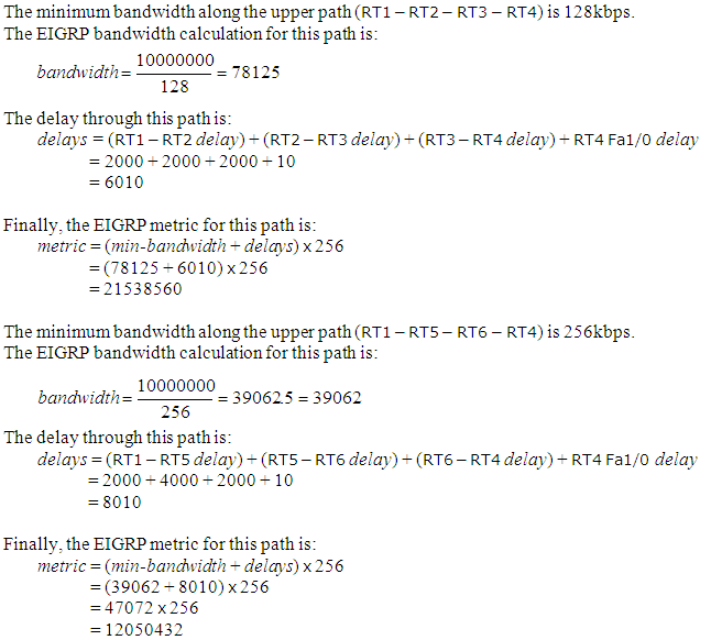
The figure above shows RT1 has 2 paths to reach 172.16.1.0/24. The bandwidth (in kbps) and delay (in tens of microseconds) of all links are also shown.


RT1 chooses the lower path over the upper path due to lower metric value. RT1 installs the route through the lower path with a next-hop of RT5 and a metric of 12050432 in its IP routing table.
RT1#sh ip eigrp topo 172.16.1.0/24
IP-EIGRP (AS 100): Topology entry for 172.16.1.0/24
  State is Passive, Query origin flag is 1, 1 Successor(s), FD is 12050432
  Routing Descriptor Blocks:
  10.10.10.6 (Serial0/1), from 10.10.10.6, Send flag is 0x0
      Composite metric is (12050432/11538432), Route is Internal
      Vector metric:
        Minimum bandwidth is 256 Kbit
        Total delay is 80100 microseconds
        Reliability is 255/255
        Load is 1/255
        Minimum MTU is 1500
        Hop count is 3

The bottleneck along the upper path is the 128kbps link between RT2 and RT3, as this means that the throughput rate through this path would be at a maximum of 128kbps. While the lowest speed along the lower path is 256kbps, allowing the throughput rate up to that speed.
Note: Bandwidth is the largest contributor upon the EIGRP metric. The delay value provides granularity when choosing the best path out from multiple paths with equivalent bandwidth.

EIGRP Neighbors

EIGRP routers can become neighbors even if the Hello and hold time values do not match, in which the Hello and hold time intervals can be set independently on different routers. The EIGRP hold time has the same function as the OSPF dead time.

EIGRP cannot form neighbor relationships using secondary addresses, as only primary addresses are used as the source IP addresses of all EIGRP packets. A neighbor relationship is formed between EIGRP routers when their primary addresses reside in the same subnet, they reside in the same AS domain, and the metric calculation constants – K values for the link are same.

EIGRP routers send out multicast Hello packets to discover neighbors and form neighborships. An EIGRP router builds a neighbor table with Hello packets received from adjacent EIGRP routers running the same routed protocol. Only adjacent routers will exchange routing updates.

When an EIGRP router discovers a new neighbor, it will send an update about its known routes to the new neighbor and receives the same information from the new neighbor. These updates are used to populate the topology table, which maintains the advertised metric from neighbors for all destinations and the metric that the local router uses to reach the destinations – feasible distance. The feasible distance metric values will be advertised to other neighbors.

EIGRP Initialization – Neighbor and Route Discovery

Below describes the steps in the EIGRP initial neighbor and route discovery process:
i) An EIGRP router (RT2) sends out a Hello packet through all its interfaces.
ii) RT1 which receives the Hello packet reply with a startup update packet that contain all its routes in its routing table (RT1 considers RT2 as its neighbor). Even though RT2 received an Update packet from RT1, it does not consider RT1 as its neighbor until it receives a Hello packet from RT1 – the EIGRP: Neighbor not yet found message will be displayed in the output of the debug eigrp neighbors privileged command. An EIGRP router considers another router as a neighbor and accepts the update information only after it received a Hello packet from the neighboring router.
iii) RT2 replies RT1 with an ACK packet, indicating the receipt of the update information.
iv) RT2 inserts the update information, which includes all destinations along with their associated metrics as advertised by neighboring routers – advertised distance.
v) Step 4, 5, and 6 are similar to Step 1, 2, and 3.
Note: Above shows a sample EIGRP neighbor establishment scenario. There are very high chances where both routers send Hello, Update, or ACK packets to each other at the same time. However, the sequence of receive Hello, reply with Update, and receive ACK will still follow.

The show ip eigrp topology EXEC command displays only the successor and feasible successor routes, as well as DUAL states which are very useful for debugging EIGRP problems. The show ip eigrp topology all-links and show ip eigrp topology detail-links EXEC commands display all entries in the topology table.
Router#sh ip eigrp topology | b 172.16.1.0
P 172.16.1.0/24, 1 successors, FD is 2172416
        via 10.10.10.2 (2172416/28160), Serial0/0
Router#
Router#sh ip eigrp topology all-links | b 172.16.1.0
P 172.16.1.0/24, 1 successors, FD is 2172416, serno 24
        via 10.10.10.2 (2172416/28160), Serial0/0
        via 10.10.10.6 (2684416/2172416), Serial0/1
Router#
Note: The highlighted path is not a feasible successor as its advertised distance is not less than the feasible distance – both values are the same.

EIGRP distinguishes itself from other routing protocols with its route selection process. EIGRP maintains successor (primary) and feasible successor (backup) routes and inserts them into the topology table (up to 6 per destination). The primary route is then inserted into the routing table.