Problem Scenario:
Cisco DCNM-LAN client shows the error message "Connectivity to the Server is lost" and become unusable after 3 minutes and 40 seconds upon successful login into the DCNM-LAN client.
You have hardened the DCNM server in which it only allow certain TCP ports to connect through the iptables firewall according to the TCP ports documented in the Cisco DCNM Installation and Licensing Guide, Release 5.x as below.
Root Cause:
Solution:
Showing posts with label security. Show all posts
Monday, October 22, 2012
Saturday, March 24, 2012
AAA - Authentication, Authorization, and Accounting
Introduction
Access control is the way to control who is allowed to access to the network devices, and what services are allowed to use once a user has been granted access (authenticated).
Authentication, Authorization, and Accounting (AAA) is the standard and common network access control security framework that has been widely implemented in Cisco networks.
Below briefly describes the functions and roles for each AAA service:
Below lists some acronyms for the main elements in AAA-based network access environment:
General AAA Configuration
Below shows the sample general AAA configuration:
The ip tacacs source-interface {type num} global configuration command specifies the IP address of an interface as the source address of the packets sent to the TACACS+ server. This ensures devices such as routers, which normally have many interfaces and IP addresses, use a specified IP address for all communications with the TACACS+ server. Additionally, the TACACS+ server uses an IP address to identify a particular device (or NAS).
Note: Normally loopback interface addresses (eg: Loopback0) would be used for routers and management interface addresses (eg: VLAN1) would be used for switches.
The tacacs-server host {ip-addr} global configuration command specifies a TACACS+ server. The tacacs-server key {key} global configuration command specifies the shared secret encryption key used for all communications between the NAS and the TACACS+ server.
Note: Multiple TACACS+ servers can also be implemented by defining a server group. However, this topic is out of the scope of this document.
The tacacs-server directed-request global configuration command configures a NAS to send only the username to a specified TACACS+ server, while the no-truncate option or the no form of this command will configure a NAS to send the whole string (both the username and hostname) to the default TACACS+ server. The directed-request mode is the default operation mode.
Example: username = root, hostname = 10.10.10.11.
TACACS+ Servers: 10.10.10.10 (default), 10.10.10.11.
root@10.10.10.11 is entered as username upon the login prompt of a NAS.
With directed-request mode, the root will be sent as the username to 10.10.10.11.
With no truncate mode, root@10.10.10.11 will be sent as the username to 10.10.10.10.
Below shows the AAA Authentication debugging messages when root@10.10.10.10 is entered as username upon the login prompt of the NAS with the directed-request mode:
Below shows AAA Authentication debugging messages when root@10.10.10.10 is entered as username upon the login prompt of the NAS with the no-truncate mode. The authentication process failed because there is no such username – root@10.10.10.10 configured in the 10.10.10.10 TACACS+ server.
The aaa new-model global configuration command is used to enable and initialize the AAA access control service.
The aaa session-id {common | unique} global configuration command specifies whether the same or different session ID will be used for each AAA accounting service type. AAA supports 6 types of accounting – EXEC, Connection, Network, Command, System, and Resource. The common is the default mode.
Note: This command is only available for Cisco IOS Release 12.2 and later. Most workgroup and access layer switches (eg: Catalyst 3550, Catalyst 2950) do not support this command.
Below shows the output of the show aaa sessions and show aaa user all EXEC commands with the aaa session-id common in effect. It shows the same session ID was used for both the EXEC and NET AAA accounting service types.
Below shows the output of the show aaa sessions and show aaa user all EXEC commands with the aaa session-id unique in effect. It shows the different session ID was used for the EXEC and NET AAA accounting service types.
Authentication Configuration
Below shows the sample AAA Authentication configuration:
The aaa authentication login {default | method-list-name} {method1} [method2…] global configuration command creates authentication method lists that define the authentication methods used to authenticate a user. An authentication method list is used in conjunction with the login authentication {method-list-name} line subcommand.
The configuration above first creates an authentication method list named local_console, which uses the local username database as the only authentication method. The authentication method list is then applied on the console (con 0) with the login authentication {method-list-name} line subcommand.
The configuration above then creates another authentication method list named ssh_telnet, which uses the TACACS+ server group as the 1st method for user authentication. The local username database is used as the backup method in case all TACACS+ servers in the server group are unavailable. The authentication method list is then applied on the Telnet / SSH virtual terminals (vty 0 4) with the login authentication {method-list-name} line subcommand.
Below shows the AAA Authentication debugging messages for the Console access to the NAS. The user root is granted access to the NAS via the console.
The local username database can be configured with the username {username} {password | secret} {password} global configuration command. Below shows the AAA Authentication debugging messages for the console access to the NAS with an unknown user:
Below shows the AAA Authentication debugging messages for the Telnet / SSH access to the NAS when the TACACS+ server is available:
Below shows the AAA Authentication debugging messages for the Telnet / SSH access to the NAS when the TACACS+ server is unavailable. An ERROR response is first received from the TACACS+ server. The NAS then tried the LOCAL authentication method.
Authorization Configuration
Below shows the sample AAA Authorization configuration:
The aaa authorization exec {default | method-list-name} {method1} [method2…] creates authorization method lists that determine whether an authenticated user will be granted an EXEC shell.
The configuration above modifies the default EXEC authorization method list named default, which uses the TACACS+ server group as the 1st method, and the local database is used as the backup method in case all TACACS+ servers in the server group are unavailable.
Below shows the AAA Authorization debugging messages for the Telnet / SSH access to the NAS when the TACACS+ server is available. An EXEC shell is granted to the user.
EXEC shell authorization can be configured in a user group or an individual user basis. User authorization overrides group authorization.
The aaa authorization commands {privilege-level} {default | method-list-name} {method1} [method2…] global configuration command creates authorization method lists that determine whether to run authorization for all commands at the specified privilege level.
The aaa authorization commands 15 ssh_telnet group tacacs+ none global configuration command creates an authorization method list named ssh_telnet, which uses the TACACS+ server group as the 1st authorization method to authorize all privilege level 15 commands (eg: show running-config, configure terminal). The none method, which means no authorization is performed, is used as the backup method in case all TACACS+ servers in the server group are unavailable.
The ssh_telnet command authorization method list is then applied on the Telnet / SSH virtual terminals (vty 0 4) with the authorization commands {privilege-level} {method-list-name} line subcommand.
Below shows the AAA Authorization debugging messages when issuing the show running-config command (a privilege level 15 command) in the NAS when the TACACS+ server is available. The user root is authorized to execute the command.
Below shows the AAA Authorization debugging messages when issuing the show running-config privileged command (a privilege level 15 command) in the NAS when the TACACS+ server is unavailable. An ERROR response is first received from the TACACS+ server. The NAS then tried the NONE authorization method. Finally the command is authorized to be executed.
Shell command authorization can be configured in a user group or an individual user basis. User authorization overrides group authorization.
The aaa authorization config-commands global configuration command enables authorization for configuration commands. Configuration command authorization is disabled by default when the aaa authorization commands global configuration command is issued.
Below shows the AAA Authorization debugging messages when the user root issues the interface FastEthernet 0/1 global configuration command without configuration command authorization in effect:
Below shows the AAA Authorization debugging messages when the user root issues the interface FastEthernet 0/1 global configuration command with configuration command authorization in effect:
Accounting Configuration
Below shows the sample AAA Accounting configuration:
The aaa accounting update newinfo global configuration command configures a NAS to send accounting records to the TACACS+ server whenever there is new accounting information to report. Additionally, another version of the command – aaa accounting update periodic {min}, configure a NAS to generate periodic accounting records continuously during active sessions, which can cause heavy congestion if many users are logged into the network.
The aaa accounting exec default start-stop group tacacs+ global configuration command configures a NAS to run accounting for both the start and stop of all the EXEC shell sessions in the NAS. The accounting records can be viewed via the TACACS+ Accounting Report.
Below shows the AAA Accounting debugging messages when the user root starts (after being authenticated) and stops an EXEC shell session.
The aaa accounting system default start-stop group tacacs+ global configuration command enables accounting for all system-level events not associated with users, eg: system reboots. Below shows the AAA Accounting debugging messages when the router is reloaded. The reload event record can be viewed via both the TACACS+ Accounting Report and TACACS+ Administration Report in the Cisco Secure ACS server.
The aaa accounting commands {privilege-level} {default | method-list-name} {start-stop | stop-only | none} group {radius | tacacs+ | server-group-name} global configuration command creates accounting method lists that determine whether to run accounting for all commands at the specified privilege level.
Below describes all the accounting notice methods:
The aaa accounting commands 15 default start-stop group tacacs+ global configuration command configures the NAS to run accounting for all privilege level 15 commands (eg: show running-config, configure terminal) and send the accounting records to the TACACS+ server.
Below shows the AAA Accounting debugging messages when the user root issues the show running-config privileged command (a privilege level 15 command) in the NAS:
Access control is the way to control who is allowed to access to the network devices, and what services are allowed to use once a user has been granted access (authenticated).
Authentication, Authorization, and Accounting (AAA) is the standard and common network access control security framework that has been widely implemented in Cisco networks.
Below briefly describes the functions and roles for each AAA service:
| Authentication | Validates the identity of a user using login and password prompting. |
| Authorization | Grants certain access privileges or rights to the services requested by the authenticated user. |
| Accounting | Provides auditing and logging functions to the security model. Tracks user access (eg: when, from where, what services have been accessed, what actions have been performed, what commands have been executed, when the command has been executed, how long the access has been lasted) in the network. Accounting records can be sent either to a remote AAA or Syslog server, and can be imported into a spreadsheet program for viewing. |
Sample AAA-Based Secure Network Access Setup
Below lists some acronyms for the main elements in AAA-based network access environment:
| NAS | Network Access Server. Act as a AAA client. |
| RADIUS | Remote Authentication Dial-in User Service. |
| TACACS+ | Terminal Access Controller Access Control System Plus. |
General AAA Configuration
Below shows the sample general AAA configuration:
Router#conf t Router(config)#ip tacacs source-interface Loopback0 Router(config)#tacacs-server host 10.10.10.10 Router(config)#tacacs-server key abc123 Router(config)#tacacs-server directed-request Router(config)#aaa new-model Router(config)#aaa session-id common Router(config)#
The ip tacacs source-interface {type num} global configuration command specifies the IP address of an interface as the source address of the packets sent to the TACACS+ server. This ensures devices such as routers, which normally have many interfaces and IP addresses, use a specified IP address for all communications with the TACACS+ server. Additionally, the TACACS+ server uses an IP address to identify a particular device (or NAS).
Note: Normally loopback interface addresses (eg: Loopback0) would be used for routers and management interface addresses (eg: VLAN1) would be used for switches.
The tacacs-server host {ip-addr} global configuration command specifies a TACACS+ server. The tacacs-server key {key} global configuration command specifies the shared secret encryption key used for all communications between the NAS and the TACACS+ server.
Note: Multiple TACACS+ servers can also be implemented by defining a server group. However, this topic is out of the scope of this document.
The tacacs-server directed-request global configuration command configures a NAS to send only the username to a specified TACACS+ server, while the no-truncate option or the no form of this command will configure a NAS to send the whole string (both the username and hostname) to the default TACACS+ server. The directed-request mode is the default operation mode.
Example: username = root, hostname = 10.10.10.11.
TACACS+ Servers: 10.10.10.10 (default), 10.10.10.11.
root@10.10.10.11 is entered as username upon the login prompt of a NAS.
With directed-request mode, the root will be sent as the username to 10.10.10.11.
With no truncate mode, root@10.10.10.11 will be sent as the username to 10.10.10.10.
Below shows the AAA Authentication debugging messages when root@10.10.10.10 is entered as username upon the login prompt of the NAS with the directed-request mode:
Router#debug aaa authentication AAA Authentication debugging is on Router# 00:05:13: AAA/AUTHEN/START (xxx): port='tty1' list='ssh_telnet' action=LOGIN service=LOGIN 00:05:13: AAA/AUTHEN/START (xxx): found list ssh_telnet 00:05:13: AAA/AUTHEN/START (xxx): Method=tacacs+ (tacacs+) 00:05:13: AAA/AUTHEN (xxx): status = GETUSER 00:05:18: AAA/AUTHEN/CONT (xxx): continue_login (user='(undef)') 00:05:18: AAA/AUTHEN (xxx): status = GETUSER 00:05:18: AAA/AUTHEN (xxx): Method=tacacs+ (tacacs+) 00:05:18: TAC+: send abort reason=Switching to directed server @ 10.10.10.10 00:05:18: AAA/AUTHEN (xxx): status = GETPASS 00:05:20: AAA/AUTHEN/CONT (xxx): continue_login (user='root') 00:05:20: AAA/AUTHEN (xxx): status = GETPASS 00:05:20: AAA/AUTHEN (xxx): Method=tacacs+ (tacacs+) 00:05:21: AAA/AUTHEN (xxx): status = PASS Router#
Below shows AAA Authentication debugging messages when root@10.10.10.10 is entered as username upon the login prompt of the NAS with the no-truncate mode. The authentication process failed because there is no such username – root@10.10.10.10 configured in the 10.10.10.10 TACACS+ server.
Router# 00:08:48: AAA/AUTHEN/START (xxx): port='tty1' list='ssh_telnet' action=LOGIN service=LOGIN 00:08:48: AAA/AUTHEN/START (xxx): found list ssh_telnet 00:08:48: AAA/AUTHEN/START (xxx): Method=tacacs+ (tacacs+) 00:08:48: AAA/AUTHEN (xxx): status = GETUSER 00:08:53: AAA/AUTHEN/CONT (xxx): continue_login (user='(undef)') 00:08:53: AAA/AUTHEN (xxx): status = GETUSER 00:08:53: AAA/AUTHEN (xxx): Method=tacacs+ (tacacs+) 00:08:53: TAC+: send abort reason=Switching to directed server @ 10.10.10.10 00:08:53: AAA/AUTHEN (xxx): status = GETPASS 00:08:55: AAA/AUTHEN/CONT (xxx): continue_login (user='root@10.10.10.10') 00:08:55: AAA/AUTHEN (xxx): status = GETPASS 00:08:55: AAA/AUTHEN (xxx): Method=tacacs+ (tacacs+) 00:08:55: AAA/AUTHEN (xxx): status = FAIL Router#
The aaa new-model global configuration command is used to enable and initialize the AAA access control service.
The aaa session-id {common | unique} global configuration command specifies whether the same or different session ID will be used for each AAA accounting service type. AAA supports 6 types of accounting – EXEC, Connection, Network, Command, System, and Resource. The common is the default mode.
Note: This command is only available for Cisco IOS Release 12.2 and later. Most workgroup and access layer switches (eg: Catalyst 3550, Catalyst 2950) do not support this command.
Below shows the output of the show aaa sessions and show aaa user all EXEC commands with the aaa session-id common in effect. It shows the same session ID was used for both the EXEC and NET AAA accounting service types.
Router>sh aaa sessions Total sessions since last reload: 1 Session Id: 110 Unique Id: 220 User Name: root IP Address: 10.10.10.2 Idle Time: 0 CT Call Handle: 0 Router> Router>sh aaa user all -------------------------------------------------- Unique id 220 is currently in use. Accounting: update method(s) : NEWINFO update interval = 0 Outstanding Stop Records : 0 EXEC: Username=root Session Id=0000006E Unique Id=000000DC Start Sent=1 Stop Only=N stop_has_been_sent=N Method List=640691B4 : Name = default Attribute list: xxxxxxxx 0 00000001 session-id(294) 4 110(6E) xxxxxxxx 0 00000001 start_time(299) 4 Mar 1 1993 00:10:49 No data for type CONN NET: Username=(n/a) Session Id=0000006E Unique Id=000000DC Start Sent=0 Stop Only=N stop_has_been_sent=N Method List=0 Attribute list: xxxxxxxx 0 00000001 session-id(294) 4 110(6E) xxxxxxxx 0 00000001 start_time(299) 4 Mar 1 1993 00:10:47 No data for type CMD No data for type SYSTEM No data for type RM CALL No data for type RM VPDN No data for type AUTH PROXY No data for type IPSEC-TUNNEL No data for type RESOURCE No data for type 10 No data for type CALL --- output omitted ---
Below shows the output of the show aaa sessions and show aaa user all EXEC commands with the aaa session-id unique in effect. It shows the different session ID was used for the EXEC and NET AAA accounting service types.
Router>sh aaa sessions Total sessions since last reload: 3 Session Id: 112 Unique Id: 221 User Name: root IP Address: 10.10.10.2 Idle Time: 0 CT Call Handle: 0 Session Id: 114 Unique Id: 221 User Name: root IP Address: 10.10.10.2 Idle Time: 0 CT Call Handle: 0 Router> Router>sh aaa user all -------------------------------------------------- Unique id 220 is currently in use. Accounting: update method(s) : NEWINFO update interval = 0 Outstanding Stop Records : 0 EXEC: Username=root Session Id=00000070 Unique Id=000000DD Start Sent=1 Stop Only=N stop_has_been_sent=N Method List=640691B4 : Name = default Attribute list: xxxxxxxx 0 00000001 session-id(294) 4 112(70) xxxxxxxx 0 00000001 start_time(299) 4 Mar 1 1993 00:11:37 No data for type CONN NET: Username=(n/a) Session Id=00000072 Unique Id=000000DD Start Sent=0 Stop Only=N stop_has_been_sent=N Method List=0 Attribute list: xxxxxxxx 0 00000001 session-id(294) 4 114(72) xxxxxxxx 0 00000001 start_time(299) 4 Mar 1 1993 00:11:35 No data for type CMD No data for type SYSTEM No data for type RM CALL No data for type RM VPDN No data for type AUTH PROXY No data for type IPSEC-TUNNEL No data for type RESOURCE No data for type 10 No data for type CALL --- output omitted ---
Authentication Configuration
Below shows the sample AAA Authentication configuration:
Router(config)#username root secret abc123 Router(config)#aaa authentication login local_console local Router(config)#aaa authentication login ssh_telnet group tacacs+ local Router(config)#line con 0 Router(config-line)#login authentication local_console Router(config-line)#exit Router(config)#line vty 0 4 Router(config-line)#login authentication ssh_telnet Router(config-line)#exit Router(config)#
The aaa authentication login {default | method-list-name} {method1} [method2…] global configuration command creates authentication method lists that define the authentication methods used to authenticate a user. An authentication method list is used in conjunction with the login authentication {method-list-name} line subcommand.
The configuration above first creates an authentication method list named local_console, which uses the local username database as the only authentication method. The authentication method list is then applied on the console (con 0) with the login authentication {method-list-name} line subcommand.
The configuration above then creates another authentication method list named ssh_telnet, which uses the TACACS+ server group as the 1st method for user authentication. The local username database is used as the backup method in case all TACACS+ servers in the server group are unavailable. The authentication method list is then applied on the Telnet / SSH virtual terminals (vty 0 4) with the login authentication {method-list-name} line subcommand.
Below shows the AAA Authentication debugging messages for the Console access to the NAS. The user root is granted access to the NAS via the console.
Router#debug aaa authentication AAA Authentication debugging is on Router# 00:15:31: AAA/AUTHEN/START (xxx): port='tty0' list='local_console' action=LOGIN service=LOGIN 00:15:31: AAA/AUTHEN/START (xxx): found list local_console 00:15:31: AAA/AUTHEN/START (xxx): Method=LOCAL 00:15:31: AAA/AUTHEN (xxx): status = GETUSER 00:15:32: AAA/AUTHEN/CONT (xxx): continue_login (user='(undef)') 00:15:32: AAA/AUTHEN (xxx): status = GETUSER 00:15:32: AAA/AUTHEN/CONT (xxx): Method=LOCAL 00:15:32: AAA/AUTHEN (xxx): status = GETPASS 00:15:34: AAA/AUTHEN/CONT (xxx): continue_login (user='root') 00:15:34: AAA/AUTHEN (xxx): status = GETPASS 00:15:34: AAA/AUTHEN/CONT (xxx): Method=LOCAL 00:15:34: AAA/AUTHEN (xxx): status = PASS Router#
The local username database can be configured with the username {username} {password | secret} {password} global configuration command. Below shows the AAA Authentication debugging messages for the console access to the NAS with an unknown user:
Router# 00:18:34: AAA/AUTHEN/START (xxx): port='tty0' list='local_console' action=LOGIN service=LOGIN 00:18:34: AAA/AUTHEN/START (xxx): found list local_console 00:18:34: AAA/AUTHEN/START (xxx): Method=LOCAL 00:18:34: AAA/AUTHEN (xxx): status = GETUSER 00:18:40: AAA/AUTHEN/CONT (xxx): continue_login (user='(undef)') 00:18:40: AAA/AUTHEN (xxx): status = GETUSER 00:18:40: AAA/AUTHEN/CONT (xxx): Method=LOCAL 00:18:40: AAA/AUTHEN (xxx): status = GETPASS 00:18:42: AAA/AUTHEN/CONT (xxx): continue_login (user='admin') 00:18:42: AAA/AUTHEN (xxx): status = GETPASS 00:18:42: AAA/AUTHEN/CONT (xxx): Method=LOCAL 00:18:42: AAA/AUTHEN (xxx): User not found 00:18:42: AAA/AUTHEN (xxx): status = FAIL Router#
Below shows the AAA Authentication debugging messages for the Telnet / SSH access to the NAS when the TACACS+ server is available:
Router# 00:20:08: AAA/AUTHEN/START (xxx): port='tty1' list='ssh_telnet' action=LOGIN service=LOGIN 00:20:08: AAA/AUTHEN/START (xxx): found list ssh_telnet 00:20:08: AAA/AUTHEN/START (xxx): Method=tacacs+ (tacacs+) 00:20:08: AAA/AUTHEN (xxx): status = GETUSER 00:20:10: AAA/AUTHEN/CONT (xxx): continue_login (user='(undef)') 00:20:10: AAA/AUTHEN (xxx): status = GETUSER 00:20:10: AAA/AUTHEN (xxx): Method=tacacs+ (tacacs+) 00:20:10: AAA/AUTHEN (xxx): status = GETPASS 00:20:11: AAA/AUTHEN/CONT (xxx): continue_login (user='root') 00:20:11: AAA/AUTHEN (xxx): status = GETPASS 00:20:11: AAA/AUTHEN (xxx): Method=tacacs+ (tacacs+) 00:20:11: AAA/AUTHEN (xxx): status = PASS Router#
Below shows the AAA Authentication debugging messages for the Telnet / SSH access to the NAS when the TACACS+ server is unavailable. An ERROR response is first received from the TACACS+ server. The NAS then tried the LOCAL authentication method.
00:20:52: AAA/AUTHEN/START (xxx): port='tty1' list='ssh_telnet' action=LOGIN service=LOGIN 00:20:52: AAA/AUTHEN/START (xxx): found list ssh_telnet 00:20:52: AAA/AUTHEN/START (xxx): Method=tacacs+ (tacacs+) 00:20:57: AAA/AUTHEN (xxx): status = ERROR 00:20:57: AAA/AUTHEN/START (xxx): Method=LOCAL 00:20:57: AAA/AUTHEN (xxx): status = GETUSER 00:21:02: AAA/AUTHEN/CONT (xxx): continue_login (user='(undef)') 00:21:02: AAA/AUTHEN (xxx): status = GETUSER 00:21:02: AAA/AUTHEN/CONT (xxx): Method=LOCAL 00:21:02: AAA/AUTHEN (xxx): status = GETPASS 00:21:04: AAA/AUTHEN/CONT (xxx): continue_login (user='root') 00:21:04: AAA/AUTHEN (xxx): status = GETPASS 00:21:04: AAA/AUTHEN/CONT (xxx): Method=LOCAL 00:21:04: AAA/AUTHEN (xxx): status = PASS
Authorization Configuration
Below shows the sample AAA Authorization configuration:
Router(config)#aaa authorization exec default group tacacs+ local Router(config)#aaa authorization commands 15 ssh_telnet group tacacs+ none Router(config)#aaa authorization config-commands Router(config)#line vty 0 4 Router(config-line)#authorization commands 15 ssh_telnet Router(config-line)#exit Router(config)#
The aaa authorization exec {default | method-list-name} {method1} [method2…] creates authorization method lists that determine whether an authenticated user will be granted an EXEC shell.
The configuration above modifies the default EXEC authorization method list named default, which uses the TACACS+ server group as the 1st method, and the local database is used as the backup method in case all TACACS+ servers in the server group are unavailable.
Below shows the AAA Authorization debugging messages for the Telnet / SSH access to the NAS when the TACACS+ server is available. An EXEC shell is granted to the user.
Router#debug aaa authorization AAA Authorization debugging is on Router# 00:24:19: tty1 AAA/AUTHOR/EXEC (xxx): Port='tty1' list='' service=EXEC 00:24:19: AAA/AUTHOR/EXEC: tty1 (xxx) user='root' 00:24:19: tty1 AAA/AUTHOR/EXEC (xxx): send AV service=shell 00:24:19: tty1 AAA/AUTHOR/EXEC (xxx): send AV cmd* 00:24:19: tty1 AAA/AUTHOR/EXEC (xxx): found list "default" 00:24:19: tty1 AAA/AUTHOR/EXEC (xxx): Method=tacacs+ (tacacs+) 00:24:19: AAA/AUTHOR/TAC+: (xxx): user=root 00:24:19: AAA/AUTHOR/TAC+: (xxx): send AV service=shell 00:24:19: AAA/AUTHOR/TAC+: (xxx): send AV cmd* 00:24:20: AAA/AUTHOR (xxx): Post authorization status = PASS_ADD 00:24:20: AAA/AUTHOR/EXEC: Authorization successful Router#
EXEC shell authorization can be configured in a user group or an individual user basis. User authorization overrides group authorization.
The aaa authorization commands {privilege-level} {default | method-list-name} {method1} [method2…] global configuration command creates authorization method lists that determine whether to run authorization for all commands at the specified privilege level.
The aaa authorization commands 15 ssh_telnet group tacacs+ none global configuration command creates an authorization method list named ssh_telnet, which uses the TACACS+ server group as the 1st authorization method to authorize all privilege level 15 commands (eg: show running-config, configure terminal). The none method, which means no authorization is performed, is used as the backup method in case all TACACS+ servers in the server group are unavailable.
The ssh_telnet command authorization method list is then applied on the Telnet / SSH virtual terminals (vty 0 4) with the authorization commands {privilege-level} {method-list-name} line subcommand.
Below shows the AAA Authorization debugging messages when issuing the show running-config command (a privilege level 15 command) in the NAS when the TACACS+ server is available. The user root is authorized to execute the command.
Router# 00:30:19: tty1 AAA/AUTHOR/CMD (xxx): Port='tty1' list='ssh_telnet' service=CMD 00:30:19: AAA/AUTHOR/CMD: tty1 (xxx) user='root' 00:30:19: tty1 AAA/AUTHOR/CMD (xxx): send AV service=shell 00:30:19: tty1 AAA/AUTHOR/CMD (xxx): send AV cmd=show 00:30:19: tty1 AAA/AUTHOR/CMD (xxx): send AV cmd-arg=running-config 00:30:19: tty1 AAA/AUTHOR/CMD (xxx): send AV cmd-arg=00:30:19: tty1 AAA/AUTHOR/CMD (xxx): found list "ssh_telnet" 00:30:19: tty1 AAA/AUTHOR/CMD (xxx): Method=tacacs+ (tacacs+) 00:30:19: AAA/AUTHOR (xxx): Post authorization status = PASS_ADD Router#
Below shows the AAA Authorization debugging messages when issuing the show running-config privileged command (a privilege level 15 command) in the NAS when the TACACS+ server is unavailable. An ERROR response is first received from the TACACS+ server. The NAS then tried the NONE authorization method. Finally the command is authorized to be executed.
Router# 00:35:45: tty1 AAA/AUTHOR/CMD (xxx): Port='tty1' list='ssh_telnet' service=CMD 00:35:45: AAA/AUTHOR/CMD: tty1 (xxx) user='root' 00:35:45: tty1 AAA/AUTHOR/CMD (xxx): send AV service=shell 00:35:45: tty1 AAA/AUTHOR/CMD (xxx): send AV cmd=show 00:35:45: tty1 AAA/AUTHOR/CMD (xxx): send AV cmd-arg=running-config 00:35:45: tty1 AAA/AUTHOR/CMD (xxx): send AV cmd-arg=00:35:45: tty1 AAA/AUTHOR/CMD (xxx): found list "ssh_telnet" 00:35:45: tty1 AAA/AUTHOR/CMD (xxx): Method=tacacs+ (tacacs+) 00:35:55: AAA/AUTHOR (xxx): Post authorization status = ERROR 00:35:55: tty1 AAA/AUTHOR/CMD (xxx): Method=NONE 00:35:55: AAA/AUTHOR (xxx): Post authorization status = PASS_ADD Router#
Shell command authorization can be configured in a user group or an individual user basis. User authorization overrides group authorization.
The aaa authorization config-commands global configuration command enables authorization for configuration commands. Configuration command authorization is disabled by default when the aaa authorization commands global configuration command is issued.
Below shows the AAA Authorization debugging messages when the user root issues the interface FastEthernet 0/1 global configuration command without configuration command authorization in effect:
Router# 00:38:50: tty1 AAA/AUTHOR/CMD (xxx): Port='tty1' list='ssh_telnet' service=CMD 00:38:50: AAA/AUTHOR/CMD: tty1 (xxx) user='root' 00:38:50: tty1 AAA/AUTHOR/CMD (xxx): send AV service=shell 00:38:50: tty1 AAA/AUTHOR/CMD (xxx): send AV cmd=configure 00:38:50: tty1 AAA/AUTHOR/CMD (xxx): send AV cmd-arg=terminal 00:38:50: tty1 AAA/AUTHOR/CMD (xxx): send AV cmd-arg=00:38:50: tty1 AAA/AUTHOR/CMD (xxx): found list "ssh_telnet" 00:38:50: tty1 AAA/AUTHOR/CMD (xxx): Method=tacacs+ (tacacs+) 00:38:51: AAA/AUTHOR (xxx): Post authorization status = PASS_ADD Router# 00:38:57: AAA/AUTHOR: config command authorization not enabled Router#
Below shows the AAA Authorization debugging messages when the user root issues the interface FastEthernet 0/1 global configuration command with configuration command authorization in effect:
Router# 00:42:38: tty1 AAA/AUTHOR/CMD (xxx): Port='tty1' list='ssh_telnet' service=CMD 00:42:38: AAA/AUTHOR/CMD: tty1 (xxx) user='root' 00:42:38: tty1 AAA/AUTHOR/CMD (xxx): send AV service=shell 00:42:38: tty1 AAA/AUTHOR/CMD (xxx): send AV cmd=interface 00:42:38: tty1 AAA/AUTHOR/CMD (xxx): send AV cmd-arg=FastEthernet 00:42:38: tty1 AAA/AUTHOR/CMD (xxx): send AV cmd-arg=0 00:42:38: tty1 AAA/AUTHOR/CMD (xxx): send AV cmd-arg=1 00:42:38: tty1 AAA/AUTHOR/CMD (xxx): send AV cmd-arg=00:42:38: tty1 AAA/AUTHOR/CMD (xxx): found list "ssh_telnet" 00:42:38: tty1 AAA/AUTHOR/CMD (xxx): Method=tacacs+ (tacacs+) 00:42:38: AAA/AUTHOR (xxx): Post authorization status = PASS_ADD Router#
Accounting Configuration
Below shows the sample AAA Accounting configuration:
Router(config)#aaa accounting update newinfo Router(config)#aaa accounting exec default start-stop group tacacs+ Router(config)#aaa accounting system default start-stop group tacacs+ Router(config)#aaa accounting commands 15 default start-stop group tacacs+
The aaa accounting update newinfo global configuration command configures a NAS to send accounting records to the TACACS+ server whenever there is new accounting information to report. Additionally, another version of the command – aaa accounting update periodic {min}, configure a NAS to generate periodic accounting records continuously during active sessions, which can cause heavy congestion if many users are logged into the network.
The aaa accounting exec default start-stop group tacacs+ global configuration command configures a NAS to run accounting for both the start and stop of all the EXEC shell sessions in the NAS. The accounting records can be viewed via the TACACS+ Accounting Report.
Below shows the AAA Accounting debugging messages when the user root starts (after being authenticated) and stops an EXEC shell session.
Router#debug aaa accounting 00:50:14: AAA/ACCT/EXEC/START User root, port tty1 00:50:14: AAA/ACCT/EXEC: Found list "default" 00:50:14: AAA/ACCT/EXEC/START User root, Port tty1, task_id=x timezone=MY service=shell 00:50:14: AAA/ACCT: user root, acct type 0 (xxx): Method=tacacs+ (tacacs+) 00:50:14: TAC+: (xxx): received acct response status = SUCCESS 00:50:30: AAA/ACCT/EXEC/STOP User root, Port tty1: task_id=x timezone=MY service=shell disc-cause=1 disc-cause-ext=xxx elapsed_time=xx nas-rx-speed=0 nas-tx-speed=0 00:50:30: AAA/ACCT: user root, acct type 0 (xxx): Method=tacacs+ (tacacs+) 00:50:30: TAC+: (xxx): received acct response status = SUCCESS Router#
The aaa accounting system default start-stop group tacacs+ global configuration command enables accounting for all system-level events not associated with users, eg: system reboots. Below shows the AAA Accounting debugging messages when the router is reloaded. The reload event record can be viewed via both the TACACS+ Accounting Report and TACACS+ Administration Report in the Cisco Secure ACS server.
Router#reload
Proceed with reload? [confirm]
00:55:21: %SYS-5-RELOAD: Reload requested
00:55:21: AAA/ACCT/unknown: task_id=x timezone=MY service=system
event=sys_acct reason=shutdown
00:55:21: AAA/ACCT: user , acct type 4 (xxx): Method=tacacs+ (tacacs+)
00:55:21: TAC+: (xxx): received acct response status = SUCCESS
The aaa accounting commands {privilege-level} {default | method-list-name} {start-stop | stop-only | none} group {radius | tacacs+ | server-group-name} global configuration command creates accounting method lists that determine whether to run accounting for all commands at the specified privilege level.
Below describes all the accounting notice methods:
| start-stop | Provides maximum accounting services. Sends a “start” and a “stop” accounting notice at both the beginning and the end of the requested process respectively. |
| stop-only | Provides minimal accounting services. Only sends a “stop” accounting notice at the end of the requested process. |
| none | Disables accounting services. |
The aaa accounting commands 15 default start-stop group tacacs+ global configuration command configures the NAS to run accounting for all privilege level 15 commands (eg: show running-config, configure terminal) and send the accounting records to the TACACS+ server.
Below shows the AAA Accounting debugging messages when the user root issues the show running-config privileged command (a privilege level 15 command) in the NAS:
Router# 00:05:02: AAA/ACCT/CMD: User root, Port tty1, Priv 15: "show running-config" 00:05:02: AAA/ACCT/CMD: Found list "default" 00:05:03: AAA/ACCT: user root, acct type 3 (xxx): Method=tacacs+ (tacacs+) 00:05:04: TAC+: (xxx): received acct response status = SUCCESS Router#
Wednesday, May 18, 2011
VPN and IPsec Basics
Virtual Private Networks (VPNs) allow the creation of private networks across a public domain (eg: Internet) for private and secured data transmission.
VPNs are secure and inexpensive. There are 2 types of VPN implementation – using IPsec to create authentication and encryption services; and establishing tunnels via tunneling protocols.
Tunneling is method of overcoming protocol restrictions by encapsulating or wrapping packets from a protocol in another protocol and transmits the encapsulated packet over a network that supports the encapsulating protocol.
Below describes the most common tunneling protocols:
Note: There are many types of tunnels. VPNs are tunnels; GRE creates tunnels; Secure Shell (SSH) is also a form of tunnel. Tunnels can encrypt data so that only the other side can see it, as with SSH; they can make a remote network appears local, as with GRE; or they can do both, as with VPN.
IPsec is a suite of industry standard network layer (L3) protocols and algorithms for securing communications over the IP-based networks by authenticating and/or encrypting IP packets. IPsec also includes the IKE protocol for establishing shared security information (Security Association, SA) between 2 network devices or end systems to support secure communication.
Note: Other Internet security protocols, eg: SSL and SSH, are operate from the Transport layer up to the Application layer (L4 – L7).
Note: The official term of “IPsec” as defined by the IETF is often wrongly addressed as “IPSec”.
IPsec secures a path between a pair of gateways, a pair of hosts, or a gateway and a host.
IPsec unable to encrypt non-IP traffic. For such a situation, a GRE tunnel would first be created to encrypt the non-IP traffic and followed by using IPsec to encrypt the GRE tunnel. Additionally, Multicast can only be passed on GRE tunnels.
IPsec-based VPN is comprised of 2 parts – Internet Key Exchange (IKE) protocol and IPsec security protocols – Authentication Header (AH) and Encapsulating Security Payload (ESP). Below describes the flow of IPsec events:
i) IKE Phase 1: IKE Security Negotiation – IKE negotiates how to protect IKE by establishing an authenticated and secure channel between 2 IKE peers called the IKE Security Association. IKE Phase 1 is consists of Main Mode or Aggressive Mode. The peer that initiates the session will propose or offer at least one or more configured ISAKMP policies which specify a combination of encryption algorithm, hash algorithm, authentication type, Diffie-Hellman group, and the lifetime. The remote peer will then try to find a matching configured policy that has the same parameters as the one being sent by its peer. If no matching policy is found, IKE will terminate the negotiation. If a policy is mutually agreed upon, IKE will complete the negotiation process and an ISAKMP SA will be created. Additionally, peers in an IPsec session must authenticate themselves among each other during IKE Phase 1 Main Mode exchange before IKE can proceed.
ii) IKE Phase 2: IPsec Security Negotiation – IKE negotiates how to protect IPsec by negotiating the IPsec security associations (SAs) and generating the keys for IPsec. IKE Phase 2 negotiation is done in only 1 mode – Quick Mode. The peer that initiates the session will propose or offer at least one or more configured transforms which specify a combination of authentication and/or encryption algorithm. The remote peer will then try to find a matching configured transform that has the same parameters as the one being sent by its peer. If no matching transform is found, IKE will terminate negotiation and an IPsec VPN will not be established. If a policy is mutually agreed upon, IKE will complete the negotiation process and an IPsec SA will be created.
iii) IPsec transfers the actual data in the VPN tunnel using the authentication and encryption methods agreed upon the IKE negotiation process.
Internet Key Exchange (IKE) allows 2 VPN endpoints verify the identity of each other (using pre-shared keys or RSA) in IKE Phase 1, and negotiate the methods (security policies) for secured data transmission in IKE Phase 2. IKE manages VPN connections by defining a set of Security Associations (SAs) for each connection. Each SA has its own SAID.
In a VPN, before a communication path is considered secure, the VPN endpoints must be authenticated. IPsec uses the following authentication methods to authenticate peers:
IKE is a hybrid protocol that uses part of Oakley and part of SKEME inside the ISAKMP framework; hence IKE is formerly known as ISAKMP/Oakley. IKE typically uses ISAKMP for key exchange and establishment of SAs, although other methods can be used.
IKE establishes both ISAKMP and IPsec SAs for an IPsec VPN session. IKE first negotiates an ISAKMP SA with the peer. It is possible to configure multiple policy statements with different parameters, and then allow the peers to negotiate and establish a mutual agreement.
An IPsec SA defines the security algorithms or parameters associated with particular connection – the IPsec protocol (AH, ESP, or both), the session keys used for data encryption, etc. IPsec SAs are unidirectional (simplex); hence there is always more than 1 IPsec SA per IPsec connection. In cases where only either AH or ESP is used, 2 SAs will be created for each connection – one for each the incoming and outgoing traffic. In cases where AH and ESP are used in conjunction, 4 SAs will be created.
The Internet Security Association and Key Management Protocol (ISAKMP) defines the procedures for authenticating peers, IKASAMP and IPsec SAs establishment, negotiation, modification, and deletion; key generation, and threat mitigation (eg: DoS and replay attacks).
Instead of ISAKMP (the use of ipsec-isakmp keyword along with the crypto map global configuration command), manual keying (the use of ipsec-manual keyword along with the crypto map global configuration command) which require manual entry of the shared secret session keys (used for hashing and encryption) on both crypto endpoints is also possible.
IPsec operation requires both ends to be configured with the same transform set, which specifies the methods for encrypt and decrypt the data. IPsec uses 2 primary security protocols – Authentication Header (AH) and Encapsulating Security Payload (ESP). These protocols are used for secured data transmission through an IPsec-based VPN tunnel. IPsec-based VPNs can be established using AH only, ESP only, or both AH and ESP.
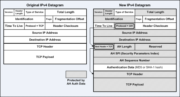
The Authentication Header (AH) protocol provides authentication for both the IP header and data of a packet using a one-way hash function. The sender first generates a one-way hash, and then the receiver generates the same one-way hash. If the packet has changed in any way, it won’t be authenticated and will be dropped. IPsec relies upon AH to guarantee authenticity. AH provides integrity check on the entire packet, but it doesn’t provide any encryption services.
ESP only provides integrity check (and encrypts) on the data of a packet (and the ESP header); while AH checks the entire packet – both header and data. AH is used for authentication only, while ESP can be used for either encryption or authentication only; or both.
Although AH and ESP are typically used independently, they are often being used together to provide data encryption service. Note: It is important to use authentication even if encryption is used, as encrypt-only implementations are subject to some forms of effective attacks.
ESP provides the following 4 functionalities or capabilities:
The degree of security of IPsec VPN is based on the encryption algorithm used and the length of the pre-shared key. The longer the key, the harder it is to be broken.
IPsec is not bound to any specific encryption or authentication algorithm, keying or technology, or security algorithms, which allows IPsec to support newer and better algorithms.
IPsec supports the following 3 types of encryption algorithms:
Encryption algorithms (eg: DES, 3DES, and AES) require a symmetric shared secret key to perform encryption and decryption. The Diffie-Hellman Key Exchange (D-H) is a public key exchange process that allows 2 parties that have no prior knowledge of each other to negotiate symmetric shared secret keys used for encryption and decryption over an insecure channel. The shared secret keys are negotiated between crypto endpoints dynamically, which only the prime modulus size for use in the D-H exchange is needed to be specified. IKE uses the D-H keys to encrypt the ISAKMP SA when establishing the IPsec SAs. Additionally, D-H is also used to generate shared secret keys to be used in the ciphers specified in the IPsec transforms, which are then used in conjunction with the D-H keys by the IPsec to encrypt and decrypt the data passes through the IPsec VPN tunnel.
IPsec uses a data integrity algorithm called Hash-based Message Authentication Code (HMAC) that adds a hash to the message to ensure data integrity. The hash guarantees the integrity of the original message. If the transmitted hash matches the received hash, the message is considered has not been tampered.
IPsec uses the following 2 HMAC algorithms:
Below lists the 2 modes of IPsec operation:
The Tunnel mode is most commonly used to secure existing IP traffic for communication between end systems on networks connected to IPsec-enabled routers. With routers or VPN endpoints performing the IPsec encryption, no changes are required to the software and drivers on the end systems – the IPsec implementation is transparent to end systems.
The main challenge and problem faced by IKE and IPsec is NAT, as both protocols were not designed to work through NAT. NAT Traversal (NAT-T) has evolved as a method of enabling IPsec-protected IP packets to work well in NAT environments by encapsulating ISAKMP and ESP packets into UDP Port 4500 packets.
The IPsec NAT Transparency feature was introduced in Cisco IOS Release 12.2T.
The access control list configuration named UDP Port 4500 as “non500-isakmp”. :-)
VPNs are secure and inexpensive. There are 2 types of VPN implementation – using IPsec to create authentication and encryption services; and establishing tunnels via tunneling protocols.
Tunneling is method of overcoming protocol restrictions by encapsulating or wrapping packets from a protocol in another protocol and transmits the encapsulated packet over a network that supports the encapsulating protocol.
Below describes the most common tunneling protocols:
| Layer 2 Forwarding (L2F) | A Cisco-proprietary tunneling protocol created for Virtual Private Dial-Up Networks (VPDNs), where devices create secure connections to a corporate network using dial-up connections. L2F was later replaced by L2TP (backward compatible with L2F). |
| Point-to-Point Tunneling Protocol (PPTP) | Created by Microsoft for secure data transmission between remote networks and corporate network. |
| Layer 2 Tunneling Protocol (L2TP) | Created by Cisco and Microsoft to replace L2F and PPTP. L2TP merged both L2F and PPTP capabilities into one tunneling protocol. |
| Generic Routing Encapsulation (GRE) | Another Cisco-proprietary tunneling protocol. It forms (unencrypted) virtual point-to-point links which are able to encapsulate a variety of protocols inside IP packets. It can also be used to protect the private address space from being advertised to any public domain. |
IPsec is a suite of industry standard network layer (L3) protocols and algorithms for securing communications over the IP-based networks by authenticating and/or encrypting IP packets. IPsec also includes the IKE protocol for establishing shared security information (Security Association, SA) between 2 network devices or end systems to support secure communication.
Note: Other Internet security protocols, eg: SSL and SSH, are operate from the Transport layer up to the Application layer (L4 – L7).
Note: The official term of “IPsec” as defined by the IETF is often wrongly addressed as “IPSec”.
IPsec secures a path between a pair of gateways, a pair of hosts, or a gateway and a host.
IPsec unable to encrypt non-IP traffic. For such a situation, a GRE tunnel would first be created to encrypt the non-IP traffic and followed by using IPsec to encrypt the GRE tunnel. Additionally, Multicast can only be passed on GRE tunnels.
IPsec-based VPN is comprised of 2 parts – Internet Key Exchange (IKE) protocol and IPsec security protocols – Authentication Header (AH) and Encapsulating Security Payload (ESP). Below describes the flow of IPsec events:
i) IKE Phase 1: IKE Security Negotiation – IKE negotiates how to protect IKE by establishing an authenticated and secure channel between 2 IKE peers called the IKE Security Association. IKE Phase 1 is consists of Main Mode or Aggressive Mode. The peer that initiates the session will propose or offer at least one or more configured ISAKMP policies which specify a combination of encryption algorithm, hash algorithm, authentication type, Diffie-Hellman group, and the lifetime. The remote peer will then try to find a matching configured policy that has the same parameters as the one being sent by its peer. If no matching policy is found, IKE will terminate the negotiation. If a policy is mutually agreed upon, IKE will complete the negotiation process and an ISAKMP SA will be created. Additionally, peers in an IPsec session must authenticate themselves among each other during IKE Phase 1 Main Mode exchange before IKE can proceed.
ii) IKE Phase 2: IPsec Security Negotiation – IKE negotiates how to protect IPsec by negotiating the IPsec security associations (SAs) and generating the keys for IPsec. IKE Phase 2 negotiation is done in only 1 mode – Quick Mode. The peer that initiates the session will propose or offer at least one or more configured transforms which specify a combination of authentication and/or encryption algorithm. The remote peer will then try to find a matching configured transform that has the same parameters as the one being sent by its peer. If no matching transform is found, IKE will terminate negotiation and an IPsec VPN will not be established. If a policy is mutually agreed upon, IKE will complete the negotiation process and an IPsec SA will be created.
iii) IPsec transfers the actual data in the VPN tunnel using the authentication and encryption methods agreed upon the IKE negotiation process.
Internet Key Exchange (IKE) allows 2 VPN endpoints verify the identity of each other (using pre-shared keys or RSA) in IKE Phase 1, and negotiate the methods (security policies) for secured data transmission in IKE Phase 2. IKE manages VPN connections by defining a set of Security Associations (SAs) for each connection. Each SA has its own SAID.
In a VPN, before a communication path is considered secure, the VPN endpoints must be authenticated. IPsec uses the following authentication methods to authenticate peers:
| Pre-Shared Keys | Secret key values that are manually configured on each peer. |
| RSA signatures | Use the exchange of digital certificates to authenticate the peers. |
IKE is a hybrid protocol that uses part of Oakley and part of SKEME inside the ISAKMP framework; hence IKE is formerly known as ISAKMP/Oakley. IKE typically uses ISAKMP for key exchange and establishment of SAs, although other methods can be used.
IKE establishes both ISAKMP and IPsec SAs for an IPsec VPN session. IKE first negotiates an ISAKMP SA with the peer. It is possible to configure multiple policy statements with different parameters, and then allow the peers to negotiate and establish a mutual agreement.
An IPsec SA defines the security algorithms or parameters associated with particular connection – the IPsec protocol (AH, ESP, or both), the session keys used for data encryption, etc. IPsec SAs are unidirectional (simplex); hence there is always more than 1 IPsec SA per IPsec connection. In cases where only either AH or ESP is used, 2 SAs will be created for each connection – one for each the incoming and outgoing traffic. In cases where AH and ESP are used in conjunction, 4 SAs will be created.
The Internet Security Association and Key Management Protocol (ISAKMP) defines the procedures for authenticating peers, IKASAMP and IPsec SAs establishment, negotiation, modification, and deletion; key generation, and threat mitigation (eg: DoS and replay attacks).
Instead of ISAKMP (the use of ipsec-isakmp keyword along with the crypto map global configuration command), manual keying (the use of ipsec-manual keyword along with the crypto map global configuration command) which require manual entry of the shared secret session keys (used for hashing and encryption) on both crypto endpoints is also possible.
IPsec operation requires both ends to be configured with the same transform set, which specifies the methods for encrypt and decrypt the data. IPsec uses 2 primary security protocols – Authentication Header (AH) and Encapsulating Security Payload (ESP). These protocols are used for secured data transmission through an IPsec-based VPN tunnel. IPsec-based VPNs can be established using AH only, ESP only, or both AH and ESP.
The Authentication Header (AH) protocol provides authentication for both the IP header and data of a packet using a one-way hash function. The sender first generates a one-way hash, and then the receiver generates the same one-way hash. If the packet has changed in any way, it won’t be authenticated and will be dropped. IPsec relies upon AH to guarantee authenticity. AH provides integrity check on the entire packet, but it doesn’t provide any encryption services.
ESP only provides integrity check (and encrypts) on the data of a packet (and the ESP header); while AH checks the entire packet – both header and data. AH is used for authentication only, while ESP can be used for either encryption or authentication only; or both.
Although AH and ESP are typically used independently, they are often being used together to provide data encryption service. Note: It is important to use authentication even if encryption is used, as encrypt-only implementations are subject to some forms of effective attacks.
ESP provides the following 4 functionalities or capabilities:
| Confidentiality (Encryption) | Provided through the use of symmetric encryption algorithms, eg: DES, 3DES. Confidentiality can be selected separately from all other services, but the confidentiality selected must be the same on all VPN endpoints. |
| Data Origin Authentication and Connectionless Integrity | Joint services offered as an option in conjunction with the confidentiality option. Authentication ensures that the connection is established with the desired system. |
| Anti-Replay Protection | This service works only if data origin authentication is selected. It is based upon the receiver – it is effective only if the receiver checks the sequence number of the received packets with a sliding window of the destination gateway or host to prevent replay attacks. |
| Traffic Flow Confidentiality | This service works only when tunnel mode is selected. It is most effective if implemented at a security gateway, where the source-destination patterns of attacks is visible. |
The degree of security of IPsec VPN is based on the encryption algorithm used and the length of the pre-shared key. The longer the key, the harder it is to be broken.
IPsec is not bound to any specific encryption or authentication algorithm, keying or technology, or security algorithms, which allows IPsec to support newer and better algorithms.
IPsec supports the following 3 types of encryption algorithms:
| Data Encryption Standard (DES) | Uses a 56-bit key that ensures high performance encryption. Uses a symmetric key cryptosystem. |
| Triple DES (3DES) | A variant of DES that breaks data into 64-bit blocks. 3DES then processes each block 3 times, each time with an independent 56-bit key, hence providing significant improvement in encryption strength over DES. Uses a symmetric key cryptosystem. |
| Advanced Encryption Standard (AES) | Provides stronger encryption than DES and is more efficient than 3DES. Key lengths can be 128-, 192-, and 256-bit keys. |
Encryption algorithms (eg: DES, 3DES, and AES) require a symmetric shared secret key to perform encryption and decryption. The Diffie-Hellman Key Exchange (D-H) is a public key exchange process that allows 2 parties that have no prior knowledge of each other to negotiate symmetric shared secret keys used for encryption and decryption over an insecure channel. The shared secret keys are negotiated between crypto endpoints dynamically, which only the prime modulus size for use in the D-H exchange is needed to be specified. IKE uses the D-H keys to encrypt the ISAKMP SA when establishing the IPsec SAs. Additionally, D-H is also used to generate shared secret keys to be used in the ciphers specified in the IPsec transforms, which are then used in conjunction with the D-H keys by the IPsec to encrypt and decrypt the data passes through the IPsec VPN tunnel.
IPsec uses a data integrity algorithm called Hash-based Message Authentication Code (HMAC) that adds a hash to the message to ensure data integrity. The hash guarantees the integrity of the original message. If the transmitted hash matches the received hash, the message is considered has not been tampered.
IPsec uses the following 2 HMAC algorithms:
| Message Digest Algorithm 5 (MD5) | Uses a 128-bit shared secret key. The message and 128-bit shared secret key are combined and run through the MD5 hash algorithm, producing a 128-bit hash. This hash is then added to the original message and sent to the destination host. |
| Secure Hash Algorithm 1 (SHA-1) | Uses a 160-bit shared secret key. The message and 160-bit shared secret key are combined and run through the SHA-1 hash algorithm, producing a 160-bit hash. This hash is then added to the original message and sent to the destination host. |
Below lists the 2 modes of IPsec operation:
| Transport | Only the payload of the IP packet is encrypted and/or authenticated. The routing is intact, as the IP header is neither modified nor encrypted. It is used for host-to-host or end-to-end communications (end systems perform the security processing). |
| Tunnel | The entire IP packet is encrypted and/or authenticated. The original packet is encapsulated entirely into a new packet with a new set of source and destination IP addresses for routing to work. It is used for network-to-network or portal-to-portal communications (gateways or routers perform the security processing). It is the traditional and default mode of IPsec VPNs. |
The Tunnel mode is most commonly used to secure existing IP traffic for communication between end systems on networks connected to IPsec-enabled routers. With routers or VPN endpoints performing the IPsec encryption, no changes are required to the software and drivers on the end systems – the IPsec implementation is transparent to end systems.
IPsec in AH Transport Mode
IPsec in AH Tunnel Mode
IPsec in ESP Transport Mode
IPsec in ESP Tunnel Mode
The main challenge and problem faced by IKE and IPsec is NAT, as both protocols were not designed to work through NAT. NAT Traversal (NAT-T) has evolved as a method of enabling IPsec-protected IP packets to work well in NAT environments by encapsulating ISAKMP and ESP packets into UDP Port 4500 packets.
The IPsec NAT Transparency feature was introduced in Cisco IOS Release 12.2T.
The access control list configuration named UDP Port 4500 as “non500-isakmp”. :-)
Friday, May 6, 2011
Unidirectional PPP CHAP Authentication
This lab demonstrates the mechanisms of unidirectional (one-way) PPP CHAP authentication. Below describes the situation of the initial lab setup:
i) Both routers have no username and PPP authentication configurations.
ii) Both routers can ping each other.
iii) Both routers have enabled PPP authentication debugging with debug ppp authentication.
The username - password statement is required on both devices for both unidirectional and bidirectional CHAP authentication. In unidirectional CHAP authentication (a local device authenticating a remote device), it is first used by the remote device (RT1) to response to the challenge generated by the local device (RT2), and then used by the local device (RT2) to verify the response from the remote device (RT1).
Below enable PPP CHAP authentication on RT2. The debugging messages show RT2 challenges RT1 but RT1 is unable to response to RT2’s challenge.
RT2(config)#int s0/0 RT2(config-if)#ppp authentication chap RT2(config-if)# 00:15:52: Se0/0 CHAP: O CHALLENGE id 1 len 24 from "RT2" 00:15:53: %LINEPROTO-5-UPDOWN: Line protocol on Interface Serial0/0, changed state to down 00:15:54: Se0/0 CHAP: O CHALLENGE id 2 len 24 from "RT2" 00:15:56: Se0/0 CHAP: O CHALLENGE id 3 len 24 from "RT2" ---------------------------------------------------------------------- RT1# 00:15:52: Se0/0 CHAP: I CHALLENGE id 1 len 24 from "RT2" 00:15:52: Se0/0 CHAP: Username RT2 not found 00:15:52: Se0/0 CHAP: Unable to authenticate for peer 00:15:52: %LINEPROTO-5-UPDOWN: Line protocol on Interface Serial0/0, changed state to down 00:15:54: Se0/0 PPP: Using default call direction 00:15:54: Se0/0 PPP: Treating connection as a dedicated line 00:15:54: Se0/0 CHAP: I CHALLENGE id 2 len 24 from "RT2" 00:15:54: Se0/0 CHAP: Username RT1 not found 00:15:54: Se0/0 CHAP: Unable to authenticate for peer 00:15:56: Se0/0 CHAP: I CHALLENGE id 3 len 24 from "RT2" 00:15:56: Se0/0 CHAP: Username RT1 not found 00:15:56: Se0/0 CHAP: Unable to authenticate for peer
Below configure the username and password on RT1. The debugging message show RT1 is able to response to RT2’s challenge but RT2 is unable to validate RT1’s response.
RT1(config)#username RT2 password cisco123 RT1(config)# 00:18:24: Se0/0 CHAP: I CHALLENGE id 67 len 24 from "RT2" 00:18:24: Se0/0 CHAP: O RESPONSE id 67 len 24 from "RT1" 00:18:24: Se0/0 CHAP: I FAILURE id 67 len 26 msg is "Authentication failure" 00:18:26: Se0/0 CHAP: I CHALLENGE id 68 len 24 from "RT2" 00:18:26: Se0/0 CHAP: O RESPONSE id 68 len 24 from "RT1" 00:18:26: Se0/0 CHAP: I FAILURE id 68 len 26 msg is "Authentication failure” ---------------------------------------------------------------------- RT2# 00:18:24: Se0/0 CHAP: O CHALLENGE id 67 len 24 from "RT2" 00:18:24: Se0/0 CHAP: I RESPONSE id 67 len 24 from "RT1" 00:18:24: Se0/0 CHAP: Unable to validate Response. Username RT1 not found 00:18:24: Se0/0 CHAP: O FAILURE id 67 len 26 msg is "Authentication failure" 00:18:26: Se0/0 CHAP: O CHALLENGE id 68 len 24 from "RT2" 00:18:26: Se0/0 CHAP: I RESPONSE id 68 len 24 from "RT1" 00:18:26: Se0/0 CHAP: Unable to validate Response. Username RT1 not found 00:18:26: Se0/0 CHAP: O FAILURE id 68 len 26 msg is "Authentication failure"Note: The alternative configuration on RT1 is the ppp chap hostname RT1 and ppp chap password cisco123 interface subcommands.
Below configure the username and password on RT2 for RT2 to validate RT1’s response.
Finally the unidirectional (one-way) PPP CHAP authentication is successful.
RT2(config)#username RT1 password cisco123 RT2(config)# 00:20:54: Se0/0 CHAP: O CHALLENGE id 127 len 24 from "RT2" 00:20:54: Se0/0 CHAP: I RESPONSE id 127 len 24 from "RT1" 00:20:54: Se0/0 CHAP: O SUCCESS id 127 len 4 00:20:54: %LINEPROTO-5-UPDOWN: Line protocol on Interface Serial0/0, changed state to up ---------------------------------------------------------------------- RT1# 00:20:48: Se0/0 CHAP: I CHALLENGE id 127 len 24 from "RT2" 00:20:48: Se0/0 CHAP: O RESPONSE id 127 len 24 from "RT1" 00:20:48: Se0/0 CHAP: I SUCCESS id 127 len 4 00:20:49: %LINEPROTO-5-UPDOWN: Line protocol on Interface Serial0/0, changed state to up 00:20:50: Se0/0 PPP: Using default call direction 00:20:50: Se0/0 PPP: Treating connection as a dedicated line
LCP packets are sent during the PPP link establishment phase. These packets contain several Configuration Option fields that allow PPP devices to negotiate how they want the link to be established – the maximum datagram size the link can carry, authentication, quality monitoring, and compression. If no Configuration Option field is present, the default configurations are used.
Unidirectional PPP PAP Authentication
Unidirectional PPP PAP authentication configuration on Client:
interface Serial0/0 ip address 10.10.10.1 255.255.255.252 encapsulation ppp ppp direction callout ppp pap sent-username Client password 0 ciscoNote: The ppp authentication pap interface subcommand is not required on Client.
Unidirectional PPP PAP authentication configuration on NAS:
username Client password 0 cisco ! interface Serial0/0 ip address 10.10.10.2 255.255.255.252 encapsulation ppp ppp authentication pap [callin] ppp direction callinNote: The callin keyword of the ppp authentication pap interface subcommand is optional
A router configured with the ppp authentication pap interface subcommand will use PAP to verify the identity of the peer, which means that the peer must present its username and password to the local device for verification. The local device would use the local username-based authentication system to verify and authenticate its peer.
The function of the username {remote-username} password {passwd} statement is different for PAP and CHAP. With PAP, it is only used to verify that an incoming username and password are valid; whereas CHAP uses it to generate the response to a challenge and verify a response.
For one-way PAP authentication, the username {remote-hostname} password {passwd} statement is only required on the called device to verify the username and password sent by the calling device; whereas for two-way PAP authentication, it is required on both devices.
A router configured with the ppp authentication pap callin interface subcommand configured will only authenticate the peer during incoming calls – it will not authenticate the peer for outgoing calls.
The ppp pap sent-username {local-username} password {passwd} interface subcommand is configured on the calling device to authenticate itself to a remote called device. The remote device must have the same set of username – password statement configured.
The ppp direction {callin | callout | dedicated} interface subcommand is introduced in Cisco IOS Release 12.2T. This command is useful when a router is connected to an interface type where there is no inherent call direction, eg: a back-to-back or leased-line connection.
Below shows the output of the PPP authentication debug messages for a successful unidirectional PAP authentication on Client:
Client#sh debug PPP: PPP authentication debugging is on PPP protocol negotiation debugging is on Client#conf t Enter configuration commands, one per line. End with CNTL/Z. Client(config)#int s1/0 Client(config-if)#no shut Client(config-if)# 00:07:14: %LINK-3-UPDOWN: Interface Serial0/0, changed state to up 00:07:14: Se0/0 PPP: Using configured call direction 00:07:14: Se0/0 PPP: Treating connection as a callout 00:07:14: Se0/0 PPP: Session handle[5A000003] Session id[25] 00:07:14: Se0/0 PPP: Phase is ESTABLISHING, Active Open 00:07:14: Se0/0 PPP: Authorization required 00:07:14: Se0/0 PPP: No remote authentication for call-out 00:07:14: Se0/0 LCP: O CONFREQ [Closed] id 25 len 10 00:07:14: Se0/0 LCP: MagicNumber 0x0013D707 (0x05060013D707) 00:07:14: Se0/0 LCP: I CONFREQ [REQsent] id 83 len 14 00:07:14: Se0/0 LCP: AuthProto PAP (0x0304C023) 00:07:14: Se0/0 LCP: MagicNumber 0x0113BFC6 (0x05060113BFC6) 00:07:14: Se0/0 LCP: O CONFACK [REQsent] id 83 len 14 00:07:14: Se0/0 LCP: AuthProto PAP (0x0304C023) 00:07:14: Se0/0 LCP: MagicNumber 0x0113BFC6 (0x05060113BFC6) 00:07:14: Se0/0 LCP: I CONFACK [ACKsent] id 25 len 10 00:07:14: Se0/0 LCP: MagicNumber 0x0013D707 (0x05060013D707) 00:07:14: Se0/0 LCP: State is Open 00:07:14: Se0/0 PPP: No authorization without authentication 00:07:15: Se0/0 PPP: Phase is AUTHENTICATING, by the peer 00:07:15: Se0/0 PAP: Using hostname from interface PAP 00:07:15: Se0/0 PAP: Using password from interface PAP 00:07:15: Se0/0 PAP: O AUTH-REQ id 25 len 17 from "Client" 00:07:15: Se0/0 PAP: I AUTH-ACK id 25 len 5 00:07:15: Se0/0 PPP: Phase is FORWARDING, Attempting Forward 00:07:15: Se0/0 PPP: Queue IPCP code[1] id[1] 00:07:15: Se0/0 PPP: Phase is ESTABLISHING, Finish LCP 00:07:15: Se0/0 PPP: Phase is UP 00:07:15: Se0/0 IPCP: O CONFREQ [Closed] id 1 len 10 00:07:15: Se0/0 IPCP: Address 10.10.10.1 (0x03060A0A0A01) 00:07:15: Se0/0 CDPCP: O CONFREQ [Closed] id 1 len 4 00:07:15: Se0/0 PPP: Process pending ncp packets 00:07:15: Se0/0 IPCP: Redirect packet to Se1/0 00:07:15: Se0/0 IPCP: I CONFREQ [REQsent] id 1 len 10 00:07:15: Se0/0 IPCP: Address 10.10.10.2 (0x03060A0A0A02) 00:07:15: Se0/0 IPCP: O CONFACK [REQsent] id 1 len 10 00:07:15: Se0/0 IPCP: Address 10.10.10.2 (0x03060A0A0A02) 00:07:15: Se0/0 CDPCP: I CONFREQ [REQsent] id 1 len 4 00:07:15: Se0/0 CDPCP: O CONFACK [REQsent] id 1 len 4 00:07:15: Se0/0 IPCP: I CONFACK [ACKsent] id 1 len 10 00:07:15: Se0/0 IPCP: Address 10.10.10.1 (0x03060A0A0A01) 00:07:15: Se0/0 IPCP: State is Open 00:07:15: Se0/0 IPCP: Add link info for cef entry 10.1.1.2 00:07:15: Se0/0 IPCP: Install route to 10.1.1.2 00:07:15: Se0/0 CDPCP: I CONFACK [ACKsent] id 1 len 4 00:07:15: Se0/0 CDPCP: State is Open 00:07:16: %LINEPROTO-5-UPDOWN: Line protocol on Interface Serial0/0, changed state to up Client(config-if)#
Below shows the output of the PPP authentication debug messages for a successful unidirectional PAP authentication on NAS:
NAS# 00:07:08: Se0/0 LCP: I CONFREQ [Listen] id 25 len 10 00:07:08: Se0/0 LCP: MagicNumber 0x0013D707 (0x05060013D707) 00:07:08: Se0/0 PPP: Authorization required 00:07:08: Se0/0 LCP: O CONFREQ [Listen] id 83 len 14 00:07:08: Se0/0 LCP: AuthProto PAP (0x0304C023) 00:07:08: Se0/0 LCP: MagicNumber 0x0113BFC6 (0x05060113BFC6) 00:07:08: Se0/0 LCP: O CONFACK [Listen] id 25 len 10 00:07:08: Se0/0 LCP: MagicNumber 0x0013D707 (0x05060013D707) 00:07:09: Se0/0 LCP: I CONFACK [ACKsent] id 83 len 14 00:07:09: Se0/0 LCP: AuthProto PAP (0x0304C023) 00:07:09: Se0/0 LCP: MagicNumber 0x0113BFC6 (0x05060113BFC6) 00:07:09: Se0/0 LCP: State is Open 00:07:09: Se0/0 PPP: Phase is AUTHENTICATING, by this end 00:07:09: Se0/0 PAP: I AUTH-REQ id 25 len 17 from "Client" 00:07:09: Se0/0 PAP: Authenticating peer Client 00:07:09: Se0/0 PPP: Phase is FORWARDING, Attempting Forward 00:07:09: Se0/0 PPP: Phase is AUTHENTICATING, Unauthenticated User 00:07:09: Se0/0 PPP: Sent PAP LOGIN Request 00:07:09: Se0/0 PPP: Received LOGIN Response PASS 00:07:09: Se0/0 PPP: Phase is FORWARDING, Attempting Forward 00:07:09: Se0/0 PPP: Phase is AUTHENTICATING, Authenticated User 00:07:09: Se0/0 PPP: Sent LCP AUTHOR Request 00:07:09: Se0/0 PPP: Sent IPCP AUTHOR Request 00:07:09: Se0/0 LCP: Received AAA AUTHOR Response PASS 00:07:09: Se0/0 IPCP: Received AAA AUTHOR Response PASS 00:07:09: Se0/0 PAP: O AUTH-ACK id 25 len 5 00:07:09: Se0/0 PPP: Phase is UP 00:07:09: Se0/0 IPCP: O CONFREQ [Closed] id 1 len 10 00:07:09: Se0/0 IPCP: Address 10.10.10.2 (0x03060A0A0A02) 00:07:09: Se0/0 PPP: Sent CDPCP AUTHOR Request 00:07:09: Se0/0 PPP: Process pending ncp packets 00:07:09: Se0/0 CDPCP: Received AAA AUTHOR Response PASS 00:07:09: Se0/0 CDPCP: O CONFREQ [Closed] id 1 len 4 00:07:09: Se0/0 IPCP: I CONFREQ [REQsent] id 1 len 10 00:07:09: Se0/0 IPCP: Address 10.10.10.1 (0x03060A0A0A01) 00:07:09: Se0/0 AAA/AUTHOR/IPCP: Start. Her address 10.1.1.1, we want 0.0.0.0 00:07:09: Se0/0 PPP: Sent IPCP AUTHOR Request 00:07:09: Se0/0 AAA/AUTHOR/IPCP: Reject 10.1.1.1, using 0.0.0.0 00:07:09: Se0/0 AAA/AUTHOR/IPCP: Done. Her address 10.1.1.1, we want 0.0.0.0 00:07:09: Se0/0 IPCP: O CONFACK [REQsent] id 1 len 10 00:07:09: Se0/0 IPCP: Address 10.10.10.1 (0x03060A0A0A01) 00:07:09: Se0/0 CDPCP: I CONFREQ [REQsent] id 1 len 4 00:07:09: Se0/0 CDPCP: O CONFACK [REQsent] id 1 len 4 00:07:09: Se0/0 IPCP: I CONFACK [ACKsent] id 1 len 10 00:07:09: Se0/0 IPCP: Address 10.10.10.2 (0x03060A0A0A02) 00:07:09: Se0/0 IPCP: State is Open 00:07:09: Se0/0 CDPCP: I CONFACK [ACKsent] id 1 len 4 00:07:09: Se0/0 CDPCP: State is Open 00:07:09: Se0/0 IPCP: Add link info for cef entry 10.1.1.1 00:07:09: Se0/0 IPCP: Install route to 10.1.1.1 00:07:10: %LINEPROTO-5-UPDOWN: Line protocol on Interface Serial0/0, changed state to up NAS#
Below shows the output of the PPP authentication debug messages for a failed unidirection PAP authentication (wrong username - password statement configured on NAS) on Client and NAS:
Client(config-if)#no shut Client(config-if)# 00:12:38: Se0/0 PPP: Phase is ESTABLISHING, Passive Open 00:12:38: Se0/0 LCP: State is Listen 00:12:38: Se0/0 LCP: State is Open 00:12:38: Se0/0 PPP: No authorization without authentication 00:12:38: Se0/0 PPP: Phase is AUTHENTICATING, by the peer 00:12:38: Se0/0 PAP: Using hostname from interface PAP 00:12:38: Se0/0 PAP: Using password from interface PAP 00:12:38: Se0/0 PAP: O AUTH-REQ id 40 len 17 from "Client" 00:12:39: Se0/0 PAP: I AUTH-NAK id 40 len 26 msg is "Authentication failed" 00:12:39: Se0/0 LCP: I TERMREQ [Open] id 134 len 4 00:12:39: Se0/0 LCP: O TERMACK [Open] id 134 len 4 00:12:39: Se0/0 PPP: Sending Acct Event[Down] id[29] 00:12:39: Se0/0 PPP: Phase is TERMINATING 00:12:41: Se0/0 LCP: TIMEout: State TERMsent 00:12:41: Se0/0 LCP: State is Closed 00:12:41: Se0/0 PPP: Phase is DOWN -------------------------------------------------- NAS# 00:12:30: Se0/0 PPP: Phase is ESTABLISHING, Passive Open 00:12:30: Se0/0 LCP: State is Listen 00:12:32: Se0/0 LCP: TIMEout: State Listen 00:12:32: Se0/0 PPP: Authorization required 00:12:32: Se0/0 LCP: State is Open 00:12:32: Se0/0 PPP: Phase is AUTHENTICATING, by this end 00:12:32: Se0/0 PAP: I AUTH-REQ id 40 len 17 from "Client" 00:12:32: Se0/0 PAP: Authenticating peer Client 00:12:32: Se0/0 PPP: Phase is FORWARDING, Attempting Forward 00:12:32: Se0/0 PPP: Phase is AUTHENTICATING, Unauthenticated User 00:12:32: Se0/0 PPP: Sent PAP LOGIN Request 00:12:32: Se0/0 PPP: Received LOGIN Response FAIL 00:12:32: Se0/0 PAP: O AUTH-NAK id 40 len 26 msg is "Authentication failed" 00:12:32: Se0/0 PPP: Sending Acct Event[Down] id[28] 00:12:32: Se0/0 PPP: Phase is TERMINATING 00:12:32: Se0/0 LCP: O TERMREQ [Open] id 134 len 4 00:12:33: Se0/0 LCP: I TERMACK [TERMsent] id 134 len 4 00:12:33: Se0/0 LCP: State is Closed 00:12:33: Se0/0 PPP: Phase is DOWN
Thursday, May 5, 2011
Directed Broadcast Forwarding
A directed broadcast is a broadcast intended for all nodes on a non-local network.
Note: The ip directed-broadcast interface subcommand which enables Directed Broadcast Forwarding for an interface only forwards directed broadcast packets from remote networks.
Ex: By enabling DBF on RT2 Fa1/0, RT2 would only forwards directed broadcast traffic sourced from networks other than 10.20.20.0.
A packet destined to the directed broadcast address 10.20.20.255 is intended for all nodes whose network address is 10.20.20.0 (PC1 and PC2). A router which does not directly connect to 10.20.20.0 (RT1) simply forwards the directed broadcast address packet to its next hop (RT2, 10.10.10.2). A router on network 10.20.20.0 (RT2) which has directed broadcast forwarding enabled on Fa1/0 would accept and forward the packet to all nodes in 10.20.20.0.
Below shows the output of the debug ip packet privileged command on RT1 and RT2 before DBF is enabled on RT2 Fa1/0. PC1 and PC2 do not response when RT1 ping 10.20.20.255.
Below shows the output of the debug ip packet privileged command on RT1 and RT2 after DBF is enabled on RT2 Fa1/0. PC1 and PC2 response to RT1 when RT1 ping 10.20.20.255.
Below shows the output of the debug ip packet privileged command on RT2 when RT2 ping 10.20.20.255. The result is same regardless of the DBF configuration on RT2 Fa1/0.
Below shows the output of the debug ip packet privileged command on RT2 when RT1 ping 255.255.255.255. PC1 and PC2 do not reply while RT2 reply when RT1 ping 255.255.255.255.
DoS (Denial-of-Service) attacks, eg: Smurf and Fraggle take advantage of directed broadcasts. Smurf attacks send a large number of ICMP Echo Request packets with a spoofed source address (victim) to a directed broadcast and cause all hosts to respond to the Echo Request packets, results in wasting network bandwidth resources and unnecessary processing on the victim host. As a result, it is recommended to disable Directed Broadcast Forwarding on any interface where directed broadcasts are not needed.
Note: The ip directed-broadcast interface subcommand which enables Directed Broadcast Forwarding for an interface only forwards directed broadcast packets from remote networks.
Ex: By enabling DBF on RT2 Fa1/0, RT2 would only forwards directed broadcast traffic sourced from networks other than 10.20.20.0.
A packet destined to the directed broadcast address 10.20.20.255 is intended for all nodes whose network address is 10.20.20.0 (PC1 and PC2). A router which does not directly connect to 10.20.20.0 (RT1) simply forwards the directed broadcast address packet to its next hop (RT2, 10.10.10.2). A router on network 10.20.20.0 (RT2) which has directed broadcast forwarding enabled on Fa1/0 would accept and forward the packet to all nodes in 10.20.20.0.
Below shows the output of the debug ip packet privileged command on RT1 and RT2 before DBF is enabled on RT2 Fa1/0. PC1 and PC2 do not response when RT1 ping 10.20.20.255.
RT2#sh run int fa1/0 Building configuration... ! interface FastEthernet1/0 ip address 10.20.20.1 255.255.255.0 end RT2#sh ip int fa1/0 FastEthernet1/0 is up, line protocol is up Internet address is 10.20.20.1/24 Directed broadcast forwarding is disabled --- output omitted --- ---------------------------------------------------------------------- RT1#ping 10.20.20.255 repeat 1 Type escape sequence to abort. Sending 1, 100-byte ICMP Echos to 10.20.20.255, timeout is 2 seconds: ! Success rate is 100 percent (1/1), round-trip min/avg/max = 44/44/44 ms RT1# 00:07:21: IP: tableid=0, s=10.10.10.1 (local), d=10.20.20.255 (FastEthernet0/0), routed via RIB 00:07:21: IP: s=10.10.10.1 (local), d=10.20.20.255 (FastEthernet0/0), len 100, sending 00:07:21: IP: tableid=0, s=10.10.10.2 (FastEthernet0/0), d=10.10.10.1 (FastEthernet0/0), routed via RIB 00:07:21: IP: s=10.10.10.2 (FastEthernet0/0), d=10.10.10.1 (FastEthernet0/0), len 100, rcvd 3 ---------------------------------------------------------------------- RT2# 00:07:21: IP: tableid=0, s=10.10.10.1 (FastEthernet0/0), d=10.20.20.255 (FastEthernet1/0), routed via RIB 00:07:21: IP: s=10.10.10.1 (FastEthernet0/0), d=10.20.20.255 (FastEthernet1/0), len100, rcvd 5 00:07:21: IP: tableid=0, s=10.10.10.2 (local), d=10.10.10.1 (FastEthernet0/0), routed via RIB 00:07:21: IP: s=10.10.10.2 (local), d=10.10.10.1 (FastEthernet0/0), len 100, sending RT2#
Below shows the output of the debug ip packet privileged command on RT1 and RT2 after DBF is enabled on RT2 Fa1/0. PC1 and PC2 response to RT1 when RT1 ping 10.20.20.255.
RT2#sh run int fa1/0 Building configuration... ! interface FastEthernet1/0 ip address 10.20.20.1 255.255.255.0 ip directed-broadcast end RT2#sh ip int fa1/0 FastEthernet1/0 is up, line protocol is up Internet address is 10.20.20.1/24 Directed broadcast forwarding is enabled --- output omitted --- -------------------------------------------------- RT1#ping 10.20.20.255 repeat 1 Type escape sequence to abort. Sending 1, 100-byte ICMP Echos to 10.20.20.255, timeout is 2 seconds: ! Success rate is 100 percent (1/1), round-trip min/avg/max = 40/40/40 ms RT1# 00:10:34: IP: tableid=0, s=10.10.10.1 (local), d=10.20.20.255 (FastEthernet0/0), routed via RIB 00:10:34: IP: s=10.10.10.1 (local), d=10.20.20.255 (FastEthernet0/0), len 100, sending 00:10:34: IP: tableid=0, s=10.10.10.2 (FastEthernet0/0), d=10.10.10.1 (FastEthernet0/0), routed via RIB 00:10:34: IP: s=10.10.10.2 (FastEthernet0/0), d=10.10.10.1 (FastEthernet0/0), len 100, rcvd 3 00:10:34: IP: tableid=0, s=10.20.20.2 (FastEthernet0/0), d=10.10.10.1 (FastEthernet0/0), routed via RIB 00:10:34: IP: s=10.20.20.2 (FastEthernet0/0), d=10.10.10.1 (FastEthernet0/0), len 100, rcvd 3 00:10:34: IP: tableid=0, s=10.20.20.3 (FastEthernet0/0), d=10.10.10.1 (FastEthernet0/0), routed via RIB 00:10:34: IP: s=10.20.20.3 (FastEthernet0/0), d=10.10.10.1 (FastEthernet0/0), len 100, rcvd 3 RT1# -------------------------------------------------- RT2# 00:10:34: IP: tableid=0, s=10.10.10.1 (FastEthernet0/0), d=10.20.20.255 (FastEthernet1/0), routed via RIB 00:10:34: IP: s=10.10.10.1 (FastEthernet0/0), d=10.20.20.255 (FastEthernet1/0), g=255.255.255.255, len 100, forward directed broadcast 00:10:34: IP: s=10.10.10.1 (FastEthernet0/0), d=10.20.20.255 (FastEthernet1/0), len100, rcvd 5 00:10:34: IP: tableid=0, s=10.10.10.2 (local), d=10.10.10.1 (FastEthernet0/0), routed via RIB 00:10:34: IP: s=10.10.10.2 (local), d=10.10.10.1 (FastEthernet0/0), len 100, sending 00:10:34: IP: tableid=0, s=10.20.20.2 (FastEthernet1/0), d=10.10.10.1 (FastEthernet0/0), routed via RIB 00:10:34: IP: s=10.20.20.2 (FastEthernet1/0), d=10.10.10.1 (FastEthernet0/0), g=10.10.10.1, len 100, forward 00:10:34: IP: tableid=0, s=10.20.20.3 (FastEthernet1/0), d=10.10.10.1 (FastEthernet0/0), routed via RIB 00:10:34: IP: s=10.20.20.3 (FastEthernet1/0), d=10.10.10.1 (FastEthernet0/0), g=10.10.10.1, len 100, forward RT2# -------------------------------------------------- PC1# xxxx: IP: s=10.10.10.1 (FastEthernet0/0), d=255.255.255.255, len 100, rcvd 2 xxxx: IP: s=10.20.20.2 (local), d=10.10.10.1 (FastEthernet0/0), len 100, sending PC1# -------------------------------------------------- PC2# xxxx: IP: s=10.10.10.1 (FastEthernet0/0), d=255.255.255.255, len 100, rcvd 2 xxxx: IP: s=10.20.20.3 (local), d=10.10.10.1 (FastEthernet0/0), len 100, sending PC2#
Below shows the output of the debug ip packet privileged command on RT2 when RT2 ping 10.20.20.255. The result is same regardless of the DBF configuration on RT2 Fa1/0.
RT2#ping 10.20.20.255 repeat 1 Type escape sequence to abort. Sending 1, 100-byte ICMP Echos to 10.20.20.255, timeout is 2 seconds: 00:14:11: IP: s=10.20.20.1 (local), d=255.255.255.255 (FastEthernet1/0), len 100, sending broad/multicast 00:14:11: IP: tableid=0, s=10.20.20.2 (FastEthernet1/0), d=10.20.20.1 (FastEthernet1/0), routed via RIB 00:14:11: IP: s=10.20.20.2 (FastEthernet1/0), d=10.20.20.1 (FastEthernet1/0), len 100, rcvd 3 00:14:11: IP: tableid=0, s=10.20.20.3 (FastEthernet1/0), d=10.20.20.1 (FastEthernet1/0), routed via RIB 00:14:11: IP: s=10.20.20.3 (FastEthernet1/0), d=10.20.20.1 (FastEthernet1/0), len 100, rcvd 3 Reply to request 0 from 10.20.20.2, 24 ms Reply to request 0 from 10.20.20.3, 40 ms RT2# -------------------------------------------------- PC1# xxxx: IP: s=10.20.20.1 (FastEthernet0/0), d=255.255.255.255, len 100, rcvd 2 xxxx: IP: s=10.20.20.2 (local), d=10.20.20.1 (FastEthernet0/0), len 100, sending PC1#
Below shows the output of the debug ip packet privileged command on RT2 when RT1 ping 255.255.255.255. PC1 and PC2 do not reply while RT2 reply when RT1 ping 255.255.255.255.
RT1#ping 255.255.255.255 rep 1
Type escape sequence to abort.
Sending 1, 100-byte ICMP Echos to 255.255.255.255, timeout is 2 seconds:
00:14:30: IP: s=10.10.10.1 (local), d=255.255.255.255 (FastEthernet0/0), len 100, sending broad/multicast
00:14:30: IP: tableid=0, s=10.10.10.2 (FastEthernet0/0), d=10.10.10.1 (FastEthernet0/0), routed via RIB
00:14:30: IP: s=10.10.10.2 (FastEthernet0/0), d=10.10.10.1 (FastEthernet0/0), len 100, rcvd 3
Reply to request 0 from 10.10.10.2, 84 ms
RT1#
--------------------------------------------------
RT2#
00:14:30: IP: s=10.10.10.1 (FastEthernet0/0), d=255.255.255.255, len 100, rcvd 2
00:14:30: IP: tableid=0, s=10.10.10.2 (local), d=10.10.10.1 (FastEthernet0/0), routed via RIB
00:14:30: IP: s=10.10.10.2 (local), d=10.10.10.1 (FastEthernet0/0), len 100, sending
RT2#
DoS (Denial-of-Service) attacks, eg: Smurf and Fraggle take advantage of directed broadcasts. Smurf attacks send a large number of ICMP Echo Request packets with a spoofed source address (victim) to a directed broadcast and cause all hosts to respond to the Echo Request packets, results in wasting network bandwidth resources and unnecessary processing on the victim host. As a result, it is recommended to disable Directed Broadcast Forwarding on any interface where directed broadcasts are not needed.
Tuesday, May 3, 2011
Switch Port Access Control Lists
Switch port ACLs can only be applied as inbound lists with extended named access lists upon L2 switch interfaces.
MAC extended access lists perform filtering based on the source and destination MAC addresses, as well as the optional EtherType information.
The question is do we really want to deny MAC addresses? Deny access based on the EtherType field in the Ethernet frame header is usually the better option.
Blocking 0x0800 would mean blocking all IP traffic, which could be handy in the future when forcing everyone to run IPv6!
MAC access lists can filter traffic based on various EtherType:
MAC extended access lists perform filtering based on the source and destination MAC addresses, as well as the optional EtherType information.
Switch#conf t Enter configuration commands, one per line. End with CNTL/Z. Switch(config)#mac access-list ? extended Extended Access List Switch(config)#mac access-list extended ? WORD access-list name Switch(config)#mac access-list extended example01 Switch(config-ext-macl)#deny any host ? H.H.H 48-bit destination MAC address Switch(config-ext-macl)#deny any host 1111.1111.1111 Switch(config-ext-macl)#permit any any Switch(config-ext-macl)#^Z Switch# Switch#sh access-list Extended MAC access list example01 deny any host 1111.1111.1111 permit any any Switch# Switch#conf t Enter configuration commands, one per line. End with CNTL/Z. Switch(config)#int fa0/1 Switch(config-if)#mac access-group example01 ? in Apply to Ingress Switch(config-if)#mac access-group example01 in Switch(config-if)#^Z Switch# Switch#sh mac access-group int fa0/1 Interface FastEthernet0/1: Inbound access-list is example01 Switch#
The question is do we really want to deny MAC addresses? Deny access based on the EtherType field in the Ethernet frame header is usually the better option.
Blocking 0x0800 would mean blocking all IP traffic, which could be handy in the future when forcing everyone to run IPv6!
MAC access lists can filter traffic based on various EtherType:
Switch(config-ext-macl)#deny any any ?
<0-65535> An arbitrary EtherType in decimal, hex, or octal
aarp EtherType: AppleTalk ARP
amber EtherType: DEC-Amber
appletalk EtherType: AppleTalk/EtherTalk
cos CoS value
dec-spanning EtherType: DEC-Spanning-Tree
decnet-iv EtherType: DECnet Phase IV
diagnostic EtherType: DEC-Diagnostic
dsm EtherType: DEC-DSM
etype-6000 EtherType: 0x6000
etype-8042 EtherType: 0x8042
lat EtherType: DEC-LAT
lavc-sca EtherType: DEC-LAVC-SCA
lsap LSAP value
mop-console EtherType: DEC-MOP Remote Console
mop-dump EtherType: DEC-MOP Dump
msdos EtherType: DEC-MSDOS
mumps EtherType: DEC-MUMPS
netbios EtherType: DEC-NETBIOS
vines-echo EtherType: VINES Echo
vines-ip EtherType: VINES IP
xns-idp EtherType: XNS IDP
<cr>
Monday, April 18, 2011
Local Proxy ARP
Below shows the output of the show ip interface {intf-type intf-num} command which shows that local proxy ARP is disabled. This section discusses what Local Proxy ARP is and its usage.
Local Proxy ARP is used when there is a need to perform proxy ARP for hosts in local network. Normally network devices do not perform local proxy ARP as they would assume the host with the requested IP address would answer the ARP request itself.
The switchport protected interface subcommand is configured on SW1 Fa0/1 and Fa0/2.
The ip local-proxy-arp interface subcommand is configured on RT3 Fa0/0.
Below shows that RT3 is performing proxy ARP for RT2:
The switchport protected interface subcommand configures a switch port as a protected port. Protected ports have the following characteristics:
1) A protected port does not forward any traffic (including unicast, multicast, and broadcast) to other protected ports – traffic cannot be forwarded between protected ports at Layer 2; all traffic between protected ports must be forwarded through a Layer 3 device.
2) Traffic between a protected port and a non-protected port is forwarded as usual.
Note: This feature applies upon a single switch, and cannot be extended across multiple switches.
Protected ports are being used in environments where traffic must not be forwarded between ports on the same switch so that an end system does not see the traffic from another end system. Below are some other sample usages of protected ports:
1) A hotel environment where the ports for each room should not be able to communicate with each other, but they need to communicate with the gateway.
2) A DMZ zone where the ports for each server should not be able to communicate with each other in order to prevent further damages of other servers when a server is owned.
3) A collocation environment where servers from different customers should not be able to communicate with each other.
Router#sh ip int fa1/0 FastEthernet1/0 is up, line protocol is up Internet address is 10.10.10.1/24 Broadcast address is 255.255.255.255 Address determined by setup command MTU is 1500 bytes Helper address is not set Directed broadcast forwarding is disabled Outgoing access list is not set Inbound access list is not set Proxy ARP is enabled Local Proxy ARP is disabled --- output omitted ---
Local Proxy ARP is used when there is a need to perform proxy ARP for hosts in local network. Normally network devices do not perform local proxy ARP as they would assume the host with the requested IP address would answer the ARP request itself.
Sample Local Proxy ARP Network
The switchport protected interface subcommand is configured on SW1 Fa0/1 and Fa0/2.
The ip local-proxy-arp interface subcommand is configured on RT3 Fa0/0.
Below shows that RT3 is performing proxy ARP for RT2:
RT1#ping 192.168.1.2 Type escape sequence to abort. Sending 5, 100-byte ICMP Echos to 17.0.0.2, timeout is 2 seconds: !!!!! Success rate is 100 percent (5/5), round-trip min/avg/max = 1/3/4 ms RT1#sh arp Protocol Address Age (min) Hardware Addr Type Interface Internet 192.168.1.1 - 1111.1111.1111 ARPA FastEthernet0/0 Internet 192.168.1.2 6 3333.3333.3333 ARPA FastEthernet0/0 Internet 192.168.1.3 5 3333.3333.3333 ARPA FastEthernet0/0
The switchport protected interface subcommand configures a switch port as a protected port. Protected ports have the following characteristics:
1) A protected port does not forward any traffic (including unicast, multicast, and broadcast) to other protected ports – traffic cannot be forwarded between protected ports at Layer 2; all traffic between protected ports must be forwarded through a Layer 3 device.
2) Traffic between a protected port and a non-protected port is forwarded as usual.
Note: This feature applies upon a single switch, and cannot be extended across multiple switches.
Protected ports are being used in environments where traffic must not be forwarded between ports on the same switch so that an end system does not see the traffic from another end system. Below are some other sample usages of protected ports:
1) A hotel environment where the ports for each room should not be able to communicate with each other, but they need to communicate with the gateway.
2) A DMZ zone where the ports for each server should not be able to communicate with each other in order to prevent further damages of other servers when a server is owned.
3) A collocation environment where servers from different customers should not be able to communicate with each other.
Subscribe to:
Posts (Atom)