Router#sh ver | in IOS|Compile
IOS (tm) 3600 Software (C3620-I-M), Version 12.3(26), RELEASE SOFTWARE (fc2)
Compiled Mon 17-Mar-08 16:20 by dchih
Router#
Router#sh alias ?
  aaa-user                 AAA user definition
  address-family           Address Family configuration mode
  boomerang                Boomerang configuration mode
  cascustom                Cas custom configuration mode
  clid-group               CLID group configuration mode
  cns-connect-config       CNS Connect Info Mode
  cns-connect-intf-config  CNS Connect Intf Info Mode
  cns-tmpl-connect-config  CNS Template Connect Info Mode
  cns_inventory_submode    CNS Inventory SubMode
  config-rtr-http-rr       RTR HTTP raw request Configuration
  config-x25-huntgroup     X.25 hunt group configuration mode
  configure                Global configuration mode
  congestion               Frame Relay congestion configuration mode
  controller               Controller configuration mode
  dhcp                     DHCP pool configuration mode
  dnis-group               DNIS group configuration mode
  exec                     Exec mode
  filterserver             AAA filter server definitions
  flow-cache               Flow aggregation cache config mode
  fr-fr                    FR/FR connection configuration mode
  interface                Interface configuration mode
  interface-dlci           Frame Relay dlci configuration mode
  interface-range          Interface range configuration mode
  ip-vrf                   Configure IP VRF parameters
  ipenacl                  IP named extended access-list configuration mode
  ipnat-pool               IP NAT pool configuration mode
  ipnat-snat               IP SNAT configuration mode
  ipnat-snat-backup        IP SNAT Backup configuration mode
  ipnat-snat-primary       IP SNAT Primary configuration mode
  ipnat-snat-redundancy    IP SNAT Redundancy configuration mode
  ipsnacl                  IP named simple access-list configuration mode
  key-chain                Key-chain configuration mode
  key-chain-key            Key-chain key configuration mode
  kron-occurrence          Kron Occurrence SubMode
  kron-policy              Kron Policy SubMode
  line                     Line configuration mode
  map-class                Map class configuration mode
  map-list                 Map list configuration mode
  mrm-manager              IP Multicast Routing Monitor config mode
  null-interface           Null interface configuration mode
  policy-list              IP Policy List configuration mode
  preauth                  AAA Preauth definitions
  qosclassmap              QoS Class Map configuration mode
  qosclasspolice           QoS Class Police configuration mode
  qospolicymap             QoS Policy Map configuration mode
  qospolicymapclass        QoS Policy Map class configuration mode
  radius-attrl             Radius Attribute-List Definition
  red-group                random-detect group configuration mode
  roles                    Role configuration mode
  route-map                Route map config mode
  router                   Router configuration mode
  rsvp-local-policy        RSVP local policy configuration mode
  rtr                      SAA entry configuration
  saa-dhcp                 SAA dhcp configuration
  saa-dns                  SAA dns configuration
  saa-echo                 SAA echo configuration
  saa-frameRelay           SAA FrameRelay configuration
  saa-ftp                  SAA ftp configuration
  saa-http                 SAA http configuration
  saa-jitter               SAA jitter configuration
  saa-pathEcho             SAA pathEcho configuration
  saa-pathJitter           SAA pathJitter configuration
  saa-tcpConnect           SAA tcpConnect configuration
  saa-udpEcho              SAA udpEcho configuration
  sg-radius                Radius Server-group Definition
  sg-tacacs+               Tacacs+ Server-group Definition
  signaling-class          Signaling class configuration mode
  subinterface             Subinterface configuration mode
  tablemap                 Table Map configuration mode
  tdm-conn                 TDM connection configuration mode
  template                 Template configuration mode
  tracking-config          Tracking configuration mode
  trange                   time-range configuration mode
  trunk-group              Trunk group configuration mode
  vc-class                 VC class configuration mode
  x25-profile              X.25 profile configuration mode
  |                        Output modifiers
  <cr>

Router#sh alias
Exec mode aliases:
  h                     help
  lo                    logout
  p                     ping
  r                     resume
  s                     show
  u                     undebug
  un                    undebug
  w                     where

Router#
Router#conf t
Enter configuration commands, one per line.  End with CNTL/Z.
Router(config)#alias ?
  aaa-user                 AAA user definition
  address-family           Address Family configuration mode
  boomerang                Boomerang configuration mode
  cascustom                Cas custom configuration mode
  clid-group               CLID group configuration mode
  cns-connect-config       CNS Connect Info Mode
  cns-connect-intf-config  CNS Connect Intf Info Mode
  cns-tmpl-connect-config  CNS Template Connect Info Mode
  cns_inventory_submode    CNS Inventory SubMode
  config-rtr-http-rr       RTR HTTP raw request Configuration
  config-x25-huntgroup     X.25 hunt group configuration mode
  configure                Global configuration mode
  congestion               Frame Relay congestion configuration mode
  controller               Controller configuration mode
  dhcp                     DHCP pool configuration mode
  dnis-group               DNIS group configuration mode
  exec                     Exec mode
  filterserver             AAA filter server definitions
  flow-cache               Flow aggregation cache config mode
  fr-fr                    FR/FR connection configuration mode
  interface                Interface configuration mode
  interface-dlci           Frame Relay dlci configuration mode
  interface-range          Interface range configuration mode
  ip-vrf                   Configure IP VRF parameters
  ipenacl                  IP named extended access-list configuration mode
  ipnat-pool               IP NAT pool configuration mode
  ipnat-snat               IP SNAT configuration mode
  ipnat-snat-backup        IP SNAT Backup configuration mode
  ipnat-snat-primary       IP SNAT Primary configuration mode
  ipnat-snat-redundancy    IP SNAT Redundancy configuration mode
  ipsnacl                  IP named simple access-list configuration mode
  key-chain                Key-chain configuration mode
  key-chain-key            Key-chain key configuration mode
  kron-occurrence          Kron Occurrence SubMode
  kron-policy              Kron Policy SubMode
  line                     Line configuration mode
  map-class                Map class configuration mode
  map-list                 Map list configuration mode
  mrm-manager              IP Multicast Routing Monitor config mode
  null-interface           Null interface configuration mode
  policy-list              IP Policy List configuration mode
  preauth                  AAA Preauth definitions
  qosclassmap              QoS Class Map configuration mode
  qosclasspolice           QoS Class Police configuration mode
  qospolicymap             QoS Policy Map configuration mode
  qospolicymapclass        QoS Policy Map class configuration mode
  radius-attrl             Radius Attribute-List Definition
  red-group                random-detect group configuration mode
  roles                    Role configuration mode
  route-map                Route map config mode
  router                   Router configuration mode
  rsvp-local-policy        RSVP local policy configuration mode
  rtr                      SAA entry configuration
  saa-dhcp                 SAA dhcp configuration
  saa-dns                  SAA dns configuration
  saa-echo                 SAA echo configuration
  saa-frameRelay           SAA FrameRelay configuration
  saa-ftp                  SAA ftp configuration
  saa-http                 SAA http configuration
  saa-jitter               SAA jitter configuration
  saa-pathEcho             SAA pathEcho configuration
  saa-pathJitter           SAA pathJitter configuration
  saa-tcpConnect           SAA tcpConnect configuration
  saa-udpEcho              SAA udpEcho configuration
  sg-radius                Radius Server-group Definition
  sg-tacacs+               Tacacs+ Server-group Definition
  signaling-class          Signaling class configuration mode
  subinterface             Subinterface configuration mode
  tablemap                 Table Map configuration mode
  tdm-conn                 TDM connection configuration mode
  template                 Template configuration mode
  tracking-config          Tracking configuration mode
  trange                   time-range configuration mode
  trunk-group              Trunk group configuration mode
  vc-class                 VC class configuration mode
  x25-profile              X.25 profile configuration mode

Router(config)#alias exec ?
  WORD  Alias name

Router(config)#alias exec siib ?
  LINE  New alias

Router(config)#alias exec siib sh ip int brief
Router(config)#end
Router#
Router#sh run | in alias
alias exec siib sh ip int brief
Router#
Router#sh alias
Exec mode aliases:
  h                     help
  lo                    logout
  p                     ping
  r                     resume
  s                     show
  u                     undebug
  un                    undebug
  w                     where
  siib                  sh ip int brief

Router#
Router#siib
Interface                  IP-Address      OK? Method Status                Protocol
FastEthernet0/0            unassigned      YES NVRAM  administratively down down
Serial1/0                  unassigned      YES NVRAM  administratively down down
Serial1/1                  unassigned      YES NVRAM  administratively down down
Serial1/2                  unassigned      YES NVRAM  administratively down down
Serial1/3                  unassigned      YES NVRAM  administratively down down
Router#
Showing posts with label tricks. Show all posts
Showing posts with label tricks. Show all posts
Sunday, October 2, 2011
The 'alias exec' Global Configuration Command
Thursday, August 25, 2011
Emulating Hosts using a Single L3 Switch

There are always cases when we need to have some hosts in testbed networks for verifying the network connectivity during network migration plan tests.
Commercial: Cisco Press - Enterprise Network Testing. :-)
I am a fans of Dynamips/Dynagen. The hosts in the 1st network setup can always be emulated using routers with IP routing disabled, configured with the "ip default-gateway" command instead of "ip route 0.0.0.0 0.0.0.0" command.
The challenge arose when I am involving in many testings and POCs on the Nexus platform switches due to the boom of the 10G data center networking and cloud, which means involving physical switches, and physical hosts.
An inefficient approach would be setting up laptops, routers, switches, etc, assigning the corresponding IP addresses, connecting the necessary power cords and UTP cables...
An efficient approach is relying upon the Virtual Device Context (VDC) concept in the Nexus 7000 Series switches, in which a physical switch can be divided into multiple logical switches, and assigning interfaces to the different logical switches, or what we called context.
This concept can also be implemented using Virtual Routing and Forwarding (VRF), which is able to assign interfaces to different virtual routers, with their own routing tables.
Below shows the configuration for implementing VRF-Lite (VRF without MPLS) on a L3 Catalyst switch to achieve the objective of having multiple hosts to reply to ICMP pings, using a single network equipment and a single power cord. :-)
en
conf t
!
hostname machines
!
ip routing
!
ip vrf PC2
ip vrf PC3
!
interface FastEthernet0/1
 no switchport
 ip address 192.168.1.101 255.255.255.0
 no shutdown
!
interface FastEthernet0/2
 no switchport
 ip vrf forwarding PC2
 ip address 192.168.1.102 255.255.255.0
 no shutdown
!
interface FastEthernet0/3
 no switchport
 ip vrf forwarding PC3
 ip address 192.168.1.103 255.255.255.0
 no shutdown
!
Verification:
machines#sh ip route
Codes: C - connected, S - static, R - RIP, M - mobile, B - BGP
       D - EIGRP, EX - EIGRP external, O - OSPF, IA - OSPF inter area
       N1 - OSPF NSSA external type 1, N2 - OSPF NSSA external type 2
       E1 - OSPF external type 1, E2 - OSPF external type 2
       i - IS-IS, su - IS-IS summary, L1 - IS-IS level-1, L2 - IS-IS level-2
       ia - IS-IS inter area, * - candidate default, U - per-user static route
       o - ODR, P - periodic downloaded static route

Gateway of last resort is not set

C    192.168.1.0/24 is directly connected, FastEthernet0/1
machines#
machines#sh ip route vrf PC2

Routing Table: PC2
Codes: C - connected, S - static, R - RIP, M - mobile, B - BGP
       D - EIGRP, EX - EIGRP external, O - OSPF, IA - OSPF inter area
       N1 - OSPF NSSA external type 1, N2 - OSPF NSSA external type 2
       E1 - OSPF external type 1, E2 - OSPF external type 2
       i - IS-IS, su - IS-IS summary, L1 - IS-IS level-1, L2 - IS-IS level-2
       ia - IS-IS inter area, * - candidate default, U - per-user static route
       o - ODR, P - periodic downloaded static route

Gateway of last resort is not set

C    192.168.1.0/24 is directly connected, FastEthernet0/2
machines#
machines#sh ip route vrf PC3

Routing Table: PC3
Codes: C - connected, S - static, R - RIP, M - mobile, B - BGP
       D - EIGRP, EX - EIGRP external, O - OSPF, IA - OSPF inter area
       N1 - OSPF NSSA external type 1, N2 - OSPF NSSA external type 2
       E1 - OSPF external type 1, E2 - OSPF external type 2
       i - IS-IS, su - IS-IS summary, L1 - IS-IS level-1, L2 - IS-IS level-2
       ia - IS-IS inter area, * - candidate default, U - per-user static route
       o - ODR, P - periodic downloaded static route

Gateway of last resort is not set

C    192.168.1.0/24 is directly connected, FastEthernet0/3
machines#
machines#debug ip icmp
ICMP packet debugging is on
machines#
machines#ping 192.168.1.102 rep 1

Type escape sequence to abort.
Sending 1, 100-byte ICMP Echos to 192.168.1.102, timeout is 2 seconds:
!
Success rate is 100 percent (1/1), round-trip min/avg/max = 9/9/9 ms
machines#
00:04:46.345: ICMP: echo reply sent, src 192.168.1.102, dst 192.168.1.101
00:04:46.345: ICMP: echo reply rcvd, src 192.168.1.102, dst 192.168.1.101
machines#
machines#ping vrf PC2 192.168.1.103 rep 1

Type escape sequence to abort.
Sending 1, 100-byte ICMP Echos to 192.168.1.103, timeout is 2 seconds:
!
Success rate is 100 percent (1/1), round-trip min/avg/max = 9/9/9 ms
machines#
00:05:06.268: ICMP: echo reply sent, src 192.168.1.103, dst 192.168.1.102
00:05:06.268: ICMP: echo reply rcvd, src 192.168.1.103, dst 192.168.1.102
machines#
Thursday, August 4, 2011
Microsoft Windows LAN Status Packets vs Bytes
The Packets and Bytes counter of the Windows LAN status is rely upon the driver.
http://support.microsoft.com/kb/296669
The following MS-DOS batch file can be used as a workaround:
http://support.microsoft.com/kb/296669
The following MS-DOS batch file can be used as a workaround:
@echo off
:REPEAT
CLS
ECHO %DATE% %TIME%
ECHO.
netstat -e
PING 1.1.1.1 -n 1 -w 800 > NUL
GOTO :REPEAT
Monday, June 20, 2011
Modifying the HTTP Header Host Field
telnet x.oanda.com 80
GET /delivery/afr.php?zoneid=1551&cb=1234567890 HTTP/1.1
Host: x.oanda.com

telnet x.oanda.com 80
GET /delivery/afr.php?zoneid=1551&cb=1234567890 HTTP/1.1
Host: www.oanda.com

Tuesday, June 14, 2011
Discovering Ethernet MTU using ICMP Ping
Windows:
C:\>ping 172.16.0.1 -n 1 -l 1472 -f

Pinging 172.16.0.1 with 1472 bytes of data:

Reply from 172.16.0.1: bytes=1472 time=1ms TTL=255

Ping statistics for 172.16.0.1:
    Packets: Sent = 1, Received = 1, Lost = 0 (0% loss),
Approximate round trip times in milli-seconds:
    Minimum = 1ms, Maximum = 1ms, Average = 1ms

C:\>
================================================================================
Cisco IOS:
Router#ping 192.168.1.2 size 1500 df-bit

Type escape sequence to abort.
Sending 5, 1500-byte ICMP Echos to 192.168.1.2, timeout is 2 seconds:
Packet sent with the DF bit set
!!!!!
Success rate is 100 percent (5/5), round-trip min/avg/max = 1/1/4 ms
Router#
================================================================================
NX-OS:
n7010# ping 192.168.1.2 packet-size 1472 df-bit
PING 192.168.1.2 (192.168.1.2): 1472 data bytes
1480 bytes from 192.168.1.2: icmp_seq=0 ttl=254 time=1.086 ms
1480 bytes from 192.168.1.2: icmp_seq=1 ttl=254 time=0.833 ms
1480 bytes from 192.168.1.2: icmp_seq=2 ttl=254 time=0.827 ms
1480 bytes from 192.168.1.2: icmp_seq=3 ttl=254 time=0.86 ms
1480 bytes from 192.168.1.2: icmp_seq=4 ttl=254 time=0.822 ms

--- 192.168.1.2 ping statistics ---
5 packets transmitted, 5 packets received, 0.00% packet loss
round-trip min/avg/max = 0.822/0.885/1.086 ms
n7010#

Saturday, April 2, 2011
Verify Load Balancing using Extended Ping

RT1#sh ip route

Gateway of last resort is not set

R    36.0.0.0/8 [120/2] via 12.12.12.2, 00:00:07, FastEthernet0/0
R    23.0.0.0/8 [120/1] via 12.12.12.2, 00:00:07, FastEthernet0/0
R    56.0.0.0/8 [120/2] via 14.14.14.4, 00:00:08, FastEthernet1/0
     12.0.0.0/24 is subnetted, 1 subnets
C       12.12.12.0 is directly connected, FastEthernet0/0
C    192.168.1.0/24 is directly connected, Loopback0
R    192.168.2.0/24 [120/3] via 14.14.14.4, 00:00:08, FastEthernet1/0
                    [120/3] via 12.12.12.2, 00:00:07, FastEthernet0/0
     14.0.0.0/24 is subnetted, 1 subnets
C       14.14.14.0 is directly connected, FastEthernet1/0
R    45.0.0.0/8 [120/1] via 14.14.14.4, 00:00:08, FastEthernet1/0
RT1#
RT1#ping 192.168.2.1 source 192.168.1.1

Type escape sequence to abort.
Sending 5, 100-byte ICMP Echos to 192.168.2.1, timeout is 2 seconds:
Packet sent with a source address of 192.168.1.1
!!!!!
Success rate is 100 percent (5/5), round-trip min/avg/max = 16/28/48 ms
RT1#
RT1#ping
Protocol [ip]:
Target IP address: 192.168.2.1
Repeat count [5]:
Datagram size [100]:
Timeout in seconds [2]:
Extended commands [n]: y
Source address or interface: 192.168.1.1
Type of service [0]:
Set DF bit in IP header? [no]:
Validate reply data? [no]:
Data pattern [0xABCD]:
Loose, Strict, Record, Timestamp, Verbose[none]: r
Number of hops [ 9 ]:
Loose, Strict, Record, Timestamp, Verbose[RV]:
Sweep range of sizes [n]:
Type escape sequence to abort.
Sending 5, 100-byte ICMP Echos to 192.168.2.1, timeout is 2 seconds:
Packet sent with a source address of 192.168.1.1
Packet has IP options:  Total option bytes= 39, padded length=40
 Record route: <*>
   (0.0.0.0)
   (0.0.0.0)
   (0.0.0.0)
   (0.0.0.0)
   (0.0.0.0)
   (0.0.0.0)
   (0.0.0.0)
   (0.0.0.0)
   (0.0.0.0)

Reply to request 0 (48 ms).  Received packet has options
 Total option bytes= 40, padded length=40
 Record route:
   (12.12.12.1)
   (23.23.23.2)
   (36.36.36.3)
   (192.168.2.1)
   (36.36.36.6)
   (23.23.23.3)
   (12.12.12.2)
   (192.168.1.1) <*>
   (0.0.0.0)
 End of list

Reply to request 1 (12 ms).  Received packet has options
 Total option bytes= 40, padded length=40
 Record route:
   (14.14.14.1)
   (45.45.45.4)
   (56.56.56.5)
   (192.168.2.1)
   (56.56.56.6)
   (45.45.45.5)
   (14.14.14.4)
   (192.168.1.1) <*>
   (0.0.0.0)
 End of list

Reply to request 2 (28 ms).  Received packet has options
 Total option bytes= 40, padded length=40
 Record route:
   (12.12.12.1)
   (23.23.23.2)
   (36.36.36.3)
   (192.168.2.1)
   (36.36.36.6)
   (23.23.23.3)
   (12.12.12.2)
   (192.168.1.1) <*>
   (0.0.0.0)
 End of list

Reply to request 3 (52 ms).  Received packet has options
 Total option bytes= 40, padded length=40
 Record route:
   (14.14.14.1)
   (45.45.45.4)
   (56.56.56.5)
   (192.168.2.1)
   (56.56.56.6)
   (45.45.45.5)
   (14.14.14.4)
   (192.168.1.1) <*>
   (0.0.0.0)
 End of list

Reply to request 4 (48 ms).  Received packet has options
 Total option bytes= 40, padded length=40
 Record route:
   (12.12.12.1)
   (23.23.23.2)
   (36.36.36.3)
   (192.168.2.1)
   (36.36.36.6)
   (23.23.23.3)
   (12.12.12.2)
   (192.168.1.1) <*>
   (0.0.0.0)
 End of list

Success rate is 100 percent (5/5), round-trip min/avg/max = 12/37/52 ms
RT1#
The Record option is very useful as it displays the addresses of the hops (up to 9) the packet goes through.
The difference between using the Record option of the extended ping command and the traceroute command is that, the Record option not only inform the hops that an ICMP Echo Request went through to get to the destination, but also inform the hops it visited on the return path (the path an ICMP Echo Reply takes).
The traceroute command does not provide such information.
The limitation is that it can only report up to a maximum of 9 hops.
Saturday, March 19, 2011
The 'keepalive' Interface Subcommand
Keepalive messages are often being sent by a network device via a physical or virtual circuit to inform another network device at the other end that the circuit between them is functioning. The keepalive mechanism on broadcast media (eg: Ethernet) is different. Since there are often many devices reside on an Ethernet network, the keepalive is not designed to determine whether the path to a particular device is available; instead, it is designed to verify that the local device has read and write access to the Ethernet media. A device would send an Ethernet frame with itself as the source and destination MAC addresses and the EtherType of 0x9000. The device would receive this frame immediately after the frame is being sent. This checks the transmit and receive hardware of an Ethernet adapter, and the integrity and quality of the cable connected to it.
Cisco implemented the Ethernet Loopback Protocol or Ethernet Configuration Test Protocol which is in the original Xerox Ethernet specification (but not in the IEEE 802.* specification).
Another well known keepalive mechanism is HDLC keepalive on Serial lines. HDLC keepalives sent between the routers at both ends are tracked and acknowledged using sequence numbers. A router declares a serial interface is down (line protocol is down) when it misses 3 keepalives.
The keepalive [interval [retries]] interface subcommand enables the sending of keepalives to itself (eg: Ethernet and Token Ring) or another end (eg: Serial and Tunnel) to ensure that an interface is operational. The parameters specify the interval between keepalives and the number of retries to continue to send keepalives without response before declaring an interface is down. The default values for interval and retries are 10 seconds and 5 retries respectively.
Ethernet link failure detection often occurs between 1 and 9 seconds. Setting the keepalive interval to a low value is very useful for rapidly detecting Ethernet interface failures.
A typical Serial line failure often caused by the lost of the Carrier Detect (CD) signal, which can be noticed within milliseconds; therefore adjusting the keepalive interval for faster routing convergence is not useful. Additionally, adjusting the keepalive interval for a very low bandwidth serial line can cause large packets to delay the delivery of small keepalive messages long enough and cause the interface to go down.
Disabling the keepalive mechanism on an Ethernet interface would stop a router from sending Ethernet Configuration Test Protocol LOOP frames.
An Ethernet interface can be enabled with the keepalive 0 or no keepalive interface subcommand when it is not being connected to a switch (or hub) port. The interface will be considered active and included in the IP routing table as a directly connected network.
Cisco implemented the Ethernet Loopback Protocol or Ethernet Configuration Test Protocol which is in the original Xerox Ethernet specification (but not in the IEEE 802.* specification).
Another well known keepalive mechanism is HDLC keepalive on Serial lines. HDLC keepalives sent between the routers at both ends are tracked and acknowledged using sequence numbers. A router declares a serial interface is down (line protocol is down) when it misses 3 keepalives.
The keepalive [interval [retries]] interface subcommand enables the sending of keepalives to itself (eg: Ethernet and Token Ring) or another end (eg: Serial and Tunnel) to ensure that an interface is operational. The parameters specify the interval between keepalives and the number of retries to continue to send keepalives without response before declaring an interface is down. The default values for interval and retries are 10 seconds and 5 retries respectively.
Ethernet link failure detection often occurs between 1 and 9 seconds. Setting the keepalive interval to a low value is very useful for rapidly detecting Ethernet interface failures.
A typical Serial line failure often caused by the lost of the Carrier Detect (CD) signal, which can be noticed within milliseconds; therefore adjusting the keepalive interval for faster routing convergence is not useful. Additionally, adjusting the keepalive interval for a very low bandwidth serial line can cause large packets to delay the delivery of small keepalive messages long enough and cause the interface to go down.
Disabling the keepalive mechanism on an Ethernet interface would stop a router from sending Ethernet Configuration Test Protocol LOOP frames.
RT1#sh int fa0/0 | in Keepalive
  Keepalive set (10 sec)
RT1#
RT1#conf t
Enter configuration commands, one per line.  End with CNTL/Z.
RT1(config)#int fa0/0
RT1(config-if)#no keepalive
RT1(config-if)#do sh int fa0/0 | in Keepalive
  Keepalive not set
An Ethernet interface can be enabled with the keepalive 0 or no keepalive interface subcommand when it is not being connected to a switch (or hub) port. The interface will be considered active and included in the IP routing table as a directly connected network.
The Cisco Router Cookie
Most Cisco routers contain an EEPROM (Electrically Erasable Programmable Read-Only Memory) which contains hardware information of a router. Some information is unique, eg: Processor board ID, Ethernet MAC address, etc; therefore it is not stored in ROM. The information is accessed by the bootstrap upon the POST (Power-On Self-Test) process. The cookie is a data structure stored in an EEPROM that is being programmed during the manufacturing process.
To display the current cookie of a router, boot the router and enter into the ROMmon mode using the break sequence, followed by entering the cookie command. The show diag EXEC command can also be used to display the contents of the cookie of a router.
Use the following formula to find out the password to enter the PRIV ROMmon mode:
password = w1 + w2 + w3 +w4 + w5 mod 216
where w1 – w5 are the first 5 words in the cookie. 216 = 65536 = 0x10000.
The PRIV password for the cookie above is B948.
The PRIV password for the following cookie is 439E.
The cookie consists of 128 bytes of data. It is normally displayed in hexadecimal format with 8 rows of 16 bytes data. Below describes the data structure of the cookie:
-
Encoding and Decoding the Processor Board ID
Follow the following steps to encode a Processor Board ID into the cookie format:
1) Convert the ASCII values of the first 3 characters to Hexadecimal.
2) Add the next 4 numbers pair-wise as they appear in the Processor Board ID.
3) Convert the ASCII values of the last 4 characters to Hexadecimal.
The result should be a series of 7 octets.
Example 1: JAE07130DAL
Answer: 0x4A 0x41 0x45 0x07 0x13 0x30 0x44 0x41 0x4C
Example 2: FCZ0929703D
Answer: 0x46 0x43 0x5A 0x09 0x29 0x37 0x30 0x33 0x44
Example 3: FTX0945W0MY
Answer: 0x46 0x54 0x58 0x09 0x45 0x57 0x30 0x4D 0x59

To display the current cookie of a router, boot the router and enter into the ROMmon mode using the break sequence, followed by entering the cookie command. The show diag EXEC command can also be used to display the contents of the cookie of a router.
System Bootstrap, Version 12.2(7r) [cmong 7r], RELEASE SOFTWARE (fc1)
Copyright (c) 2002 by cisco Systems, Inc.
C2600 platform with 131072 Kbytes of main memory

PC = 0xfff0ac3c, Vector = 0x500, SP = 0x800043b4

monitor: command "boot" aborted due to user interrupt
rommon 1 > cookie
cookie:
01 01 00 0c 85 bb ef 60 43 20 80 ff 03 6e 00 20
00 00 00 00 00 00 00 00 4a 41 45 07 13 30 44 41
4c 01 00 00 00 00 00 00 00 ff ff ff 58 06 49 1e
4b 02 ff ff ff ff ff ff ff ff ff ff ff ff ff ff
ff ff ff ff ff ff ff ff ff ff ff ff ff ff ff ff
ff ff ff ff ff ff ff ff ff ff ff ff ff ff ff ff
ff ff ff ff ff ff ff ff ff ff ff ff ff ff ff ff
ff ff ff ff ff ff ff ff ff ff ff ff ff ff ff ff
rommon 2 >
Use the following formula to find out the password to enter the PRIV ROMmon mode:
password = w1 + w2 + w3 +w4 + w5 mod 216
where w1 – w5 are the first 5 words in the cookie. 216 = 65536 = 0x10000.
The PRIV password for the cookie above is B948.
01 01 00 0c 85 bb ef 60 43 20 80 ff 03 6e 00 20
00 00 00 00 00 00 00 00 4a 41 45 07 13 30 44 41
4c 01 00 00 00 00 00 00 00 ff ff ff 58 06 49 1e
4b 02 ff ff ff ff ff ff ff ff ff ff ff ff ff ff
ff ff ff ff ff ff ff ff ff ff ff ff ff ff ff ff
ff ff ff ff ff ff ff ff ff ff ff ff ff ff ff ff
ff ff ff ff ff ff ff ff ff ff ff ff ff ff ff ff
ff ff ff ff ff ff ff ff ff ff ff ff ff ff ff ff

     0x0101
     0x000C
     0x85BB
     0xEF60
   + 0x4320
   --------
    0x1B948
mod 0x10000
   --------
     0xB948
   --------
The PRIV password for the following cookie is 439E.
01 01 00 12 d9 ab 25 c0 43 20 80 ff 03 6e 00 20
00 00 00 00 00 00 00 00 46 43 5a 09 29 37 30 33
44 04 00 00 00 00 00 00 00 ff ff ff 50 06 49 1e
4b 06 ff ff ff ff ff ff ff ff ff ff ff ff ff ff
46 4f 43 08 50 33 38 53 56 43 20 00 00 00 00 00
ff ff ff ff ff ff ff ff ff ff ff ff ff ff ff ff
ff ff ff ff ff ff ff ff ff ff ff ff ff ff ff ff
ff ff ff ff ff ff ff ff ff ff ff ff ff ff ff ff

     0x0101
     0x0012
     0xD9AB
     0x25C0
   + 0x4320
   --------
    0x1439E
mod 0x10000
   --------
     0x439E
   --------
The cookie consists of 128 bytes of data. It is normally displayed in hexadecimal format with 8 rows of 16 bytes data. Below describes the data structure of the cookie:
-
| Index | Size | Name | Description |
| 0x00 | 1 | Version | Indicates the version of the cookie format. 0x01 – Cisco 2600 Series. |
| 0x01 | 1 | Vendor | The vendor of the device. It is assumed that this value is always 0x01, as the vendor is always Cisco. |
| 0x02 | 6 | Ethernet Hardware Address | The BIA Ethernet MAC address of the 1st integrated Ethernet interface. |
| 0x08 | 1 | Processor | Indicates the type of processor (e_machine). The actual reason that a router unable to boot when the cookie is corrupt is that it compares the e_machine values in the cookie and flash image file. If these 2 values do not match, the router assumes that the image file is invalid for its platform and therefore refuses to load it. |
| 0x09 | 1 | NVRAM Size | The size index of the NVRAM. Note: This value is not the size of NVRAM in Kbytes. |
| 0x0a | 1 | CPU Speed | The speed index of the CPU. Note: It doesn’t indicate the CPU speed in MHz. |
| 0x0b | 1 | Unused | - |
| 0x0c | 2 | On-board PM ID | Not sure. |
| 0x0e | 2 | MAC Address allocated | Not sure. |
| 0x10 | 8 | Unknown | - |
| 0x18 | 9 | Processor Board ID | Indicates the encoded Processor Board ID, which is printed on a label on the router motherboard. The Processor Board ID can be different than the serial number of the router. |
| 0x21 | 2 | CPU Revision | Referred to as the Processor Revision number |
| 0x23 | 2 | Deviation | Referred to as the Hardware Revision number. |
| 0x25 | 7 | Unknown | - |
| 0x2c | 1 | CPU Type | Indicates the type of CPU (cpu_type). |
| 0x2d | 1 | Board Config | Not sure. |
| 0x2e | 4 | Unknown | - |
| 0x32 | 6 | WAN MAC Address | Not sure. |
| 0x38 | 72 | Unused |
Encoding and Decoding the Processor Board ID
Follow the following steps to encode a Processor Board ID into the cookie format:
1) Convert the ASCII values of the first 3 characters to Hexadecimal.
2) Add the next 4 numbers pair-wise as they appear in the Processor Board ID.
3) Convert the ASCII values of the last 4 characters to Hexadecimal.
The result should be a series of 7 octets.
Example 1: JAE07130DAL
| J | A | E | 07 | 13 | 0 | D | A | L |
| 0x4A | 0x41 | 0x45 | 0x07 | 0x13 | 0x30 | 0x44 | 0x41 | 0x4C |
Example 2: FCZ0929703D
| F | C | Z | 09 | 29 | 7 | 0 | 3 | D |
| 0x46 | 0x43 | 0x5A | 0x09 | 0x29 | 0x37 | 0x30 | 0x33 | 0x44 |
Example 3: FTX0945W0MY
| F | T | X | 09 | 45 | W | 0 | M | Y |
| 0x46 | 0x54 | 0x58 | 0x09 | 0x45 | 0x57 | 0x30 | 0x4D | 0x59 |
ASCII Conversion Chart
Thursday, March 17, 2011
Cisco SLARP
Cisco HDLC (cHDLC) is the Cisco-proprietary extension to the High-Level Data Link Control (HDLC), a data link layer protocol that was originally developed by the International Organization for Standardization (ISO). The primary reason for the creation of cHDLC is to address the limitation of multiprotocol support – there is no Protocol field defined for identifying the encapsulated L3 network protocols.
The Cisco HDLC extension also includes the definition of Serial Line Address Resolution Protocol (SLARP). SLARP provides dynamic address assignment between 2 endpoints across a serial link, as well as a keepalive mechanism for ensuring the availability of a serial link.
The keepalive mechanism works by carrying the sequence numbers in the SLARP frames. The sequence numbers are incremented for each keepalive sent. The health of the serial link can be determined by each endpoint by keeping track of the sequence. The serial link goes down (line protocol down) after a certain number of sequence numbers is missed (keepalive lost).
Below shows how SLARP dynamically assign an IP address for a router interface resides on a /30 point-to-point serial link:
RT2#sh run int s0/0
Building configuration...

Current configuration : 52 bytes
!
interface Serial0/0
 no ip address
 shutdown
end

RT2#
RT2#conf t
Enter configuration commands, one per line.  End with CNTL/Z.
RT2(config)#int s0/0
RT2(config-if)#ip address ?
  A.B.C.D     IP address
  negotiated  IP Address negotiated over PPP
  pool        IP Address autoconfigured from a local DHCP pool
  slarp       Set IP address through SLARP

RT2(config-if)#ip address slarp ?
  retry  Define retry time interval

RT2(config-if)#ip address slarp retry ?
  <1-60>  Retry timer interval, from 1 to 60 seconds

RT2(config-if)#ip address slarp retry 10
RT2(config-if)#no shut
RT2(config-if)#^Z
RT2#
00:22:47.799: %SYS-5-CONFIG_I: Configured from console by console
00:22:49.363: %LINK-3-UPDOWN: Interface Serial0/0, changed state to up
00:22:50.367: %LINEPROTO-5-UPDOWN: Line protocol on Interface Serial0/0, changed state to up
00:23:05.099: %LINK-5-SLARP: Serial0/0 address 10.10.10.2, resolved by 10.10.10.1
RT2#
RT2#sh ip int brief
Interface          IP-Address      OK? Method Status                Protocol
Serial0/0          10.10.10.2      YES SLARP  up                    up
Serial0/1          unassigned      YES unset  administratively down down
Serial0/2          unassigned      YES unset  administratively down down
Serial0/3          unassigned      YES unset  administratively down down
FastEthernet1/0    unassigned      YES unset  administratively down down
RT2#
RT2#ping 10.10.10.1

Type escape sequence to abort.
Sending 5, 100-byte ICMP Echos to 10.10.10.1, timeout is 2 seconds:
!!!!!
Success rate is 100 percent (5/5), round-trip min/avg/max = 16/31/44 ms
RT2#
RT2#sh cdp neighbors detail | in Device ID|IP address|Interface
-------------------------
Device ID: RT1
  IP address: 10.10.10.1
Interface: Serial0/0,  Port ID (outgoing port): Serial0/0
RT2#
RT2#sh run int s0/0
Building configuration...

Current configuration : 93 bytes
!
interface Serial0/0
 ip address 10.10.10.2 255.255.255.252
 ip address slarp retry 10
end

RT2#
RT2#sh ip int s0/0
Serial0/0 is up, line protocol is up
  Internet address is 10.10.10.2/30
  Broadcast address is 255.255.255.255
  Address determined by Reverse ARP from host 10.10.10.1
--- output omitted ---
Saturday, March 12, 2011
Debug using Access Control List
Below shows a sample debug session using access list on Cisco IOS Release 12.3:
Note: The debug ip packet privileged command is only effective for packets originated from and destined to the device.
RT1#sh run int fa0/0
Building configuration...

Current configuration : 97 bytes
!
interface FastEthernet0/0
 ip address 10.10.10.1 255.255.255.252
 duplex auto
 speed auto
end

RT1#
RT1#sh run | in access-list 101
access-list 101 permit icmp host 10.10.10.1 any
RT1#
RT1#debug ip packet 101
IP packet debugging is on for access list 101
RT1#
RT1#sh debug
Generic IP:
  IP packet debugging is on for access list 101
RT1#
RT1#ping ip 10.10.10.2 source 10.10.10.1 size 1600 repeat 1

Type escape sequence to abort.
Sending 1, 1600-byte ICMP Echos to 10.10.10.2, timeout is 2 seconds:
Packet sent with a source address of 10.10.10.1
!
Success rate is 100 percent (1/1), round-trip min/avg/max = 44/44/44 ms
RT1#
00:12:31: IP: tableid=0, s=10.10.10.1 (local), d=10.10.10.2 (FastEthernet0/0), routed via FIB
00:12:31: IP: s=10.10.10.1 (local), d=10.10.10.2 (FastEthernet0/0), len 1600, sending
00:12:31: IP: s=10.10.10.1 (local), d=10.10.10.2 (FastEthernet0/0), len 1500, sending fragment
00:12:31: IP: s=10.10.10.1 (local), d=10.10.10.2 (FastEthernet0/0), len 120, sending last fragment
RT1#
Note: The debug ip packet privileged command is only effective for packets originated from and destined to the device.
Access List Sequence Number
Below shows a sample configuration for modifying access lists using sequence numbers:
Router#conf t
Enter configuration commands, one per line.  End with CNTL/Z.
Router(config)#access-list 101 deny ip 10.10.10.0 0.0.0.255 any
Router(config)#do sh access-list 101
Extended IP access list 101
    10 deny ip 10.10.10.0 0.0.0.255 any
Router(config)#
Router(config)#ip access-list extended 101
Router(config-ext-nacl)#?
Ext Access List configuration commands:
  <1-2147483647>  Sequence Number
  default         Set a command to its defaults
  deny            Specify packets to reject
  dynamic         Specify a DYNAMIC list of PERMITs or DENYs
  evaluate        Evaluate an access list
  exit            Exit from access-list configuration mode
  no              Negate a command or set its defaults
  permit          Specify packets to forward
  remark          Access list entry comment

Router(config-ext-nacl)#5 permit ip host 10.10.10.10 host 11.11.11.11
Router(config-ext-nacl)#do sh access-list
Extended IP access list 101
    5 permit ip host 10.10.10.10 host 11.11.11.11
    10 deny ip 10.10.10.0 0.0.0.255 any
Router(config-ext-nacl)#
Router(config-ext-nacl)#no 5
Router(config-ext-nacl)#do sh access-list
Extended IP access list 101
    10 deny ip 10.10.10.0 0.0.0.255 any
Router(config-ext-nacl)#no 10
Router(config-ext-nacl)#do sh access-list

Router(config-ext-nacl)#
Router(config-ext-nacl)#do sh run | in access-list
Router(config-ext-nacl)#
Inserting Question Marks in Cisco IOS CLI
Question marks can be inserted into literal strings, eg: interface descriptions, by typing CTRL+V immediately before the question mark. It acts as an escape sequence and prevents the command line from summoning the context-sensitive help menu.
Router#conf t
Enter configuration commands, one per line.  End with CNTL/Z.
Router(config)#int fa0/0
Router(config-if)#desc ### Testing[CTRL+V]? ###
Router(config-if)#
Router(config-if)#do sh int desc
Interface                      Status         Protocol Description
Fa0/0                          admin down     down     *** Testing? ***
Router(config-if)#
Friday, March 11, 2011
Enabling SSH on Cisco Device
Below shows the procedure for enabling SSH on a Cisco router:
Router#conf t
Enter configuration commands, one per line.  End with CNTL/Z.
Router(config)#crypto key generate rsa
% Please define a hostname other than Router.
Router(config)#hostname RT1
RT1(config)#crypto key generate rsa
% Please define a domain-name first.
RT1(config)#ip domain-name test.com
RT1(config)#crypto key generate rsa
The name for the keys will be: RT1.test.com
Choose the size of the key modulus in the range of 360 to 2048 for your
  General Purpose Keys. Choosing a key modulus greater than 512 may take
  a few minutes.

How many bits in the modulus [512]: 1024
Generating RSA keys ...
[OK]

RT1(config)#
00:00:37: %SSH-5-ENABLED: SSH 1.99 has been enabled
RT1(config)#^Z
RT1#
RT1#sh ip ssh
SSH Enabled - version 1.99
Authentication timeout: 120 secs; Authentication retries: 3
RT1#
RT1#sh ssh
%No SSHv2 server connections running.
%No SSHv1 server connections running.
RT1#
RT1#sh crypto key mypubkey rsa
% Key pair was generated at: 10:31:59 UTC Nov 20 2008
Key name: RT1.test.com
 Usage: General Purpose Key
 Key Data:
  30819F30 0D06092A 864886F7 0D010101 05000381 8D003081 89028181 00B357DC
  9A834E22 90813C9C 467F5347 4BB44A47 C4D988F5 9E5B304E DC5F49C0 D99615CF
  03D1A53B 084163BD 645AE36F 559D23C5 CB22846D EDE9C149 9837B6C7 BD98D546
  9329F7C9 4619ACE5 CD4B8884 C6630F03 6DDFE0D6 C24BE740 874A68D4 332FAF18
  A1DB3452 9A87BC2C 380E288D BA8E57F0 056225B9 7C9EE898 EDE73C22 C5020301 0001
% Key pair was generated at: 10:32:01 UTC Nov 20 2008
Key name: RT1.test.com.server
 Usage: Encryption Key
 Key Data:
  307C300D 06092A86 4886F70D 01010105 00036B00 30680261 00AE50E8 5BAE5D43
  A407A61F 8F6FCEF2 28A308B7 612B8375 0DD76815 3816538F F43D1D42 7927EC08
  FBDE6411 4C44BBC5 C4D39744 77D98109 FD0D8234 DDF5E75C FA51538C 327EA2A9
  29BB5D7D 47458336 24A78731 1FAA5570 03F7893A B7530A62 65020301 0001
RT1#
RT1#conf t
Enter configuration commands, one per line.  End with CNTL/Z.
RT1(config)#crypto key zeroize rsa
% Keys to be removed are named RT1.test.com.
Do you really want to remove these keys? [yes/no]: yes
RT1(config)#
00:03:12: %SSH-5-DISABLED: SSH 1.99 has been disabled
RT1(config)#^Z
RT1#
RT1#sh ip ssh
SSH Disabled - version 1.99
%Please create RSA keys to enable SSH.
RT1#
RT1#sh crypto key mypubkey rsa
RT1#
Tuesday, March 8, 2011
Show Active Cisco IOS Processes
The show process cpu sorted EXEC command which is issued with the combinations of output filters can be used to display only those active IOS processes that consumed noticeable amount of CPU time and resource over the last 5 seconds, 1 minute, and 5 minutes.
The following patterns are used to construct the regular expressions for the mentioned purpose:
i) The [0-9.]+% pattern will match any non-zero percentage value;
ii) The 0.00% pattern will match the zero percentage value;
iii) As the percentage values are separated by various amounts of space characters, the + pattern is used to match those.
The output filters should exclude the processes that have the zero percentage in the desired column and any percentage value in the other 2 columns.
Below shows the exact show commands used to display the active processes in the last 5 minutes, 1 minute, and 5 seconds.
Below shows a sample output from a router:
The following patterns are used to construct the regular expressions for the mentioned purpose:
i) The [0-9.]+% pattern will match any non-zero percentage value;
ii) The 0.00% pattern will match the zero percentage value;
iii) As the percentage values are separated by various amounts of space characters, the + pattern is used to match those.
The output filters should exclude the processes that have the zero percentage in the desired column and any percentage value in the other 2 columns.
Below shows the exact show commands used to display the active processes in the last 5 minutes, 1 minute, and 5 seconds.
| 5 secs | show process cpu sorted 5sec | exclude 0.00% +[0-9.]+% +[0-9.]+% |
| 1 min | show process cpu sorted 1min | exclude [0-9.]+% +0.00% +[0-9.]+% |
| 5 mins | show process cpu sorted 5min | exclude [0-9.]+% +[0-9.]+% +0.00% |
Below shows a sample output from a router:
Router>show process cpu sorted 5sec | exclude 0.00% +[0-9.]+% +[0-9.]+%
CPU utilization for five seconds: 18%/3%; one minute: 22%; five minutes: 21%
 PID Runtime(ms)   Invoked      uSecs   5Sec   1Min   5Min TTY Process
 141   262418490  83111379       3157 11.70% 13.51% 13.41%   0 encrypt proc
   5     7832705    443427      17664  2.21%  0.46%  0.37%   0 Check heaps
  56    19292254  16716172       1154  0.16%  0.80%  0.89%   0 IP Input
 100     1172442   4098350        286  0.16%  0.07%  0.06%   0 DHCPD Receive
 211     1093462  63950042         17  0.16%  0.07%  0.06%   0 PPP Events
   2     1947017    411375       4732  0.08%  0.09%  0.08%   0 Load Meter
 210     1411416  63950011         22  0.08%  0.07%  0.07%   0 PPP manager
 116      370688   3280908        112  0.08%  0.03%  0.00%   0 CEF process
 114      308130   8423193         36  0.08%  0.02%  0.00%   0 Inspect Timer
Router>
Router>show process cpu sorted 1min | exclude [0-9.]+% +0.00% +[0-9.]+%
CPU utilization for five seconds: 18%/3%; one minute: 22%; five minutes: 21%
 PID Runtime(ms)   Invoked      uSecs   5Sec   1Min   5Min TTY Process
 141   262418586  83111423       3157 11.70% 13.51% 13.41%   0 encrypt proc
 144       11148     85202        130  0.00%  3.01%  2.11%  66 Virtual Exec
  56    19292270  16716188       1154  0.16%  0.80%  0.89%   0 IP Input
   5     7832705    443427      17664  2.21%  0.46%  0.37%   0 Check heaps
   2     1947017    411375       4732  0.08%  0.09%  0.08%   0 Load Meter
 210     1411416  63950063         22  0.08%  0.07%  0.07%   0 PPP manager
 211     1093462  63950094         17  0.16%  0.07%  0.06%   0 PPP Events
 100     1172446   4098354        286  0.16%  0.07%  0.06%   0 DHCPD Receive
 116      370692   3280911        112  0.08%  0.03%  0.00%   0 CEF process
 114      308130   8423203         36  0.08%  0.02%  0.00%   0 Inspect Timer
   8      364776    480408        759  0.00%  0.01%  0.00%   0 ARP Input
 217      960116    154212       6225  0.00%  0.01%  0.01%   0 SNMP ENGINE
Router>
Download Cisco IOS Software Image using the 'tftpdnld' ROMmon Command
rommon 1 > set
PS1=rommon ! >
BSI=0
WARM_REBOOT=FALSE
RANDOM_NUM=1067305006
RET_2_RTS=07:54:29 UTC Fri Aug 29 2008
RET_2_RCALTS=1219996473
?=0
rommon 2 > IP_ADDRESS=192.168.1.2
rommon 3 > IP_SUBNET_MASK=255.255.255.0
rommon 4 > DEFAULT_GATEWAY=192.168.1.1
rommon 5 > TFTP_SERVER=192.168.1.1
rommon 6 > TFTP_FILE=xxx.bin
rommon 7 > tftpdnld

          IP_ADDRESS: 192.168.1.2
      IP_SUBNET_MASK: 255.255.255.0
     DEFAULT_GATEWAY: 192.168.1.1
         TFTP_SERVER: 192.168.1.1
           TFTP_FILE: xxx.bin
        TFTP_MACADDR: 00:23:04:b2:eb:c6
        TFTP_VERBOSE: Progress
    TFTP_RETRY_COUNT: 18
        TFTP_TIMEOUT: 7200
       TFTP_CHECKSUM: Yes
             FE_PORT: 0
       FE_SPEED_MODE: Auto Detect

Invoke this command for disaster recovery only.
WARNING: all existing data in all partitions on flash: will be lost!
Do you wish to continue? y/n:  [n]:  n

TFTP download aborted - user request
rommon 8 >
rommon 8 > set
PS1=rommon ! >
BSI=0
WARM_REBOOT=FALSE
RANDOM_NUM=1067305006
RET_2_RTS=07:54:29 UTC Fri Aug 29 2008
RET_2_RCALTS=1219996473
IP_ADDRESS=192.168.1.2
IP_SUBNET_MASK=255.255.255.0
DEFAULT_GATEWAY=192.168.1.1
TFTP_SERVER=192.168.1.1
TFTP_FILE=xxx.bin
?=38
rommon 9 >
Sunday, March 6, 2011
Adding Timestamps to "show" Commands – "terminal exec prompt timestamp"
Router>terminal exec prompt timestamp
Router>sh clock
Load for five secs: 1%/0%; one minute: 5%; five minutes: 1%
No time source, *00:00:13.911 UTC Mon Mar 1 1993

*00:00:13.911 UTC Mon Mar 1 1993
Router>
The exec prompt timestamp line subcommand enables this feature on particular terminal lines.
Decrypting Type 7 Password using Cisco IOS
Router#conf t
Enter configuration commands, one per line.  End with CNTL/Z.
Router(config)#key chain decrypt01
Router(config-keychain)#key 1
Router(config-keychain-key)#key-string 7 05080F1C22431F5B4A
Router(config-keychain-key)#end
Router#
Router#sh key chain decrypt01 or sh key chain
Key-chain decrypt01:
    key 1 -- text "cisco123"
        accept lifetime (always valid) - (always valid) [valid now]
        send lifetime (always valid) - (always valid) [valid now]
Router#
Cisco IOS Tcl Ping Script
The Cisco IOS Scripting with Tcl feature was first introduced on Cisco IOS Release 12.3(2)T.
Tcl – Tool Command Language
Tcl – Tool Command Language
Router#conf t
Enter configuration commands, one per line.  End with CNTL/Z.
Router(config)#interface Loopback1
Router(config-if)#ip address 1.1.1.1 255.255.255.255
Router(config-if)#exit
Router(config)#
Router(config)#interface Loopback3
Router(config-if)#ip address 3.3.3.3 255.255.255.255
Router(config-if)#exit
Router(config)#end
Router#
Router#tclsh
Router(tcl)#foreach ip {
+>1.1.1.1
+>2.2.2.2
+>3.3.3.3
+>} {
+>ping $ip
+>}

Type escape sequence to abort.
Sending 5, 100-byte ICMP Echos to 1.1.1.1, timeout is 2 seconds:
!!!!!
Success rate is 100 percent (5/5), round-trip min/avg/max = 8/10/12 ms
Type escape sequence to abort.
Sending 5, 100-byte ICMP Echos to 2.2.2.2, timeout is 2 seconds:
.....
Success rate is 0 percent (0/5)
Type escape sequence to abort.
Sending 5, 100-byte ICMP Echos to 3.3.3.3, timeout is 2 seconds:
!!!!!
Success rate is 100 percent (5/5), round-trip min/avg/max = 8/10/12 ms
Router(tcl)#
Router(tcl)#foreach ip {
+>1.1.1.1
+>2.2.2.2
+>3.3.3.3
+>} {
+>if { [regexp "(!!!)" [exec "ping $ip timeout 1" ]] } {
+>puts $ip
+>} else { puts "$ip *** failed ***" }
+>}
1.1.1.1
2.2.2.2 *** failed ***
3.3.3.3

Router(tcl)#
Router(tcl)#exit
Router#
Thursday, March 3, 2011
Cisco IOS Prefix List
Prefix lists are used to match IP prefixes, with the capability to match an exact prefix length or a prefix range. Prefix lists are often used as the alternative over access lists and distribute lists. Prefix lists are faster and less CPU-intensive than regular access lists and distribute lists. Prefix list entries can be deleted and added individually.
The formats of a prefix list entry and an IP access control list (ACL) entry are similar. A prefix list entry consists of a name, an action (deny or permit), the prefix number, and the prefix length. The syntax of the command is ip prefix-list {list-name} [seq seq-num] {deny | permit} {prefix/length} [ge ge-value] [le le-value]. The network number can be any valid IP address or prefix, while the bit mask can be a number from 0 to 32. The prefix is automatically converted to match the prefix length value, eg: entering 10.11.12.0/8 would result in 10.0.0.0/8.
Note: If a prefix is permitted, the route will be used; if a prefix is denied, the route is not used.
The basic form of prefix list assumes an exact match of both prefix number and prefix length. Additional parameters are required to match a range of prefixes. When a prefix range ends at /32, the ge-value (greater-than-or-equal-to) can be specified. The ge-value must be greater than the length specified by the prefix/length parameter, and less than 32. When the ge parameter is specified, the prefixes with mask length from the ge-value to 32 (inclusive) will be matched.
If the prefix length does not end at /32, the le (less-than-or-equal-to) parameter must be specified. When both the ge and le parameters are specified, the prefixes with mask length between the ge-value and le-value (inclusive) will be matched. The specified ge-value and le-value must satisfy the following condition:

Below is an example of using both the ge and le parameters to match a portion of 172.16.1.0/24:
ip prefix-list pl-test permit 172.16.1.0/24 ge 25 le 30
Note that 172.16.1.0/24 and all the /31s and /32s are not in the range.
Below lists the prefixes that are being matched by the prefix range:
When a prefix list is configured without a sequence number, the default sequence number of 5 will be applied to the prefix list, and subsequent prefix list entries will be incremented by 5, eg: 5, 10, 15, etc. If a sequence number is entered for the first prefix list entry but not subsequent entries, the subsequent entries will also be incremented by 5, eg: if the first configured sequence number is 3, then the subsequent sequence numbers will be 8, 13, 18, etc.
Below lists some examples of prefix lists:
The sample network above was setup to observe how RT2 uses prefix lists to determine which subnets to be redistributed from OSPF into EIGRP.
Below shows the configuration on RT2:
Below shows the routing table on RT3:
The formats of a prefix list entry and an IP access control list (ACL) entry are similar. A prefix list entry consists of a name, an action (deny or permit), the prefix number, and the prefix length. The syntax of the command is ip prefix-list {list-name} [seq seq-num] {deny | permit} {prefix/length} [ge ge-value] [le le-value]. The network number can be any valid IP address or prefix, while the bit mask can be a number from 0 to 32. The prefix is automatically converted to match the prefix length value, eg: entering 10.11.12.0/8 would result in 10.0.0.0/8.
Note: If a prefix is permitted, the route will be used; if a prefix is denied, the route is not used.
The basic form of prefix list assumes an exact match of both prefix number and prefix length. Additional parameters are required to match a range of prefixes. When a prefix range ends at /32, the ge-value (greater-than-or-equal-to) can be specified. The ge-value must be greater than the length specified by the prefix/length parameter, and less than 32. When the ge parameter is specified, the prefixes with mask length from the ge-value to 32 (inclusive) will be matched.
If the prefix length does not end at /32, the le (less-than-or-equal-to) parameter must be specified. When both the ge and le parameters are specified, the prefixes with mask length between the ge-value and le-value (inclusive) will be matched. The specified ge-value and le-value must satisfy the following condition:
prefix-length < ge-value < le-value ≤ 32
Representation of Prefix Length Ranges for the ip prefix-list Command
Below is an example of using both the ge and le parameters to match a portion of 172.16.1.0/24:
ip prefix-list pl-test permit 172.16.1.0/24 ge 25 le 30
Note that 172.16.1.0/24 and all the /31s and /32s are not in the range.
Below lists the prefixes that are being matched by the prefix range:
| 2 /25s | 172.16.1.0/25, 172.16.1.128/25. |
| 4 /26s | 172.16.1.0/26, 172.16.1.64/26, 172.16.1.128/26, 172.16.1.192/26. |
| 8 /27s | 172.16.1.0/27, 172.16.1.32/27 … 172.16.1.192/27, 172.16.1.224/27. |
| 16 /28s | 172.16.1.0/28, 172.16.1.16/28 … 172.16.1.224/28, 172.16.1.240/28. |
| 32 /29s | 172.16.1.0/29, 172.16.1.8/29 … 172.16.1.240/29, 172.16.1.248/29. |
| 64 /30s | 172.16.1.0/30, 172.16.1.4/30 … 172.16.1.248/30, 172.16.1.252/30. |
When a prefix list is configured without a sequence number, the default sequence number of 5 will be applied to the prefix list, and subsequent prefix list entries will be incremented by 5, eg: 5, 10, 15, etc. If a sequence number is entered for the first prefix list entry but not subsequent entries, the subsequent entries will also be incremented by 5, eg: if the first configured sequence number is 3, then the subsequent sequence numbers will be 8, 13, 18, etc.
Below lists some examples of prefix lists:
| ip prefix-list pl-test permit 0.0.0.0/0 A prefix list entry configured to match only the default route 0.0.0.0/0. |
| ip prefix-list pl-test permit 0.0.0.0/0 le 32 A prefix list entry configured to match any address or subnet – match all (permit any any). |
| ip prefix-list pl-test permit 0.0.0.0/0 ge 8 le 24 A prefix list entry configured to match any prefix that has a prefix length from 8 to 24 bits. |
| ip prefix-list pl-test permit 0.0.0.0/0 ge 30 le 30 A prefix list entry configured to match any prefix with prefix length of 30. |
| ip prefix-list pl-test permit 172.16.1.0/24 A prefix list entry configured to match the 172.16.1.0/24 subnet. |
| ip prefix-list pl-test permit 10.0.0.0/8 le 24 A prefix list entry configured to match subnets from the 10.0.0.0/8 network that have a prefix length that is less than or equal to 24 bits. |
| ip prefix-list pl-test permit 10.0.0.0/8 ge 25 A prefix list entry configured to match subnets from the 10.0.0.0/8 network that have a prefix length that is greater than or equal to 25 bits. |
| ip prefix-list pl-test permit 10.0.0.0/8 le 32 A prefix list entry configured to match any prefix from the 10.0.0.0/8 network. |
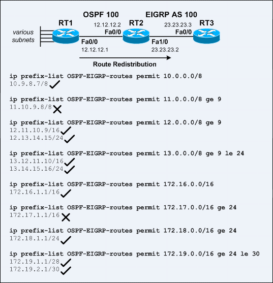
Network Setup for IP Prefix Lists
The sample network above was setup to observe how RT2 uses prefix lists to determine which subnets to be redistributed from OSPF into EIGRP.
Below shows the configuration on RT2:
!
router ospf 100
 network 12.12.12.2 0.0.0.0 area 0
!
router eigrp 100
 redistribute ospf 100 route-map OSPF-EIGRP
 network 23.23.23.2 0.0.0.0
 default-metric 10000 100 255 1 1500
 no auto-summary
!
ip prefix-list OSPF-EIGRP-routes seq 5 permit 10.0.0.0/8
ip prefix-list OSPF-EIGRP-routes seq 10 permit 11.0.0.0/8 ge 9
ip prefix-list OSPF-EIGRP-routes seq 15 permit 12.0.0.0/8 ge 9
ip prefix-list OSPF-EIGRP-routes seq 20 permit 13.0.0.0/8 ge 9 le 24
ip prefix-list OSPF-EIGRP-routes seq 25 permit 172.16.0.0/16
ip prefix-list OSPF-EIGRP-routes seq 30 permit 172.17.0.0/16 ge 24
ip prefix-list OSPF-EIGRP-routes seq 35 permit 172.18.0.0/16 ge 24
ip prefix-list OSPF-EIGRP-routes seq 40 permit 172.19.0.0/16 ge 24 le 30
!
route-map OSPF-EIGRP permit 10
 match ip address prefix-list OSPF-EIGRP-routes
!
Below shows the routing table on RT3:
RT3#sh ip route

Gateway of last resort is not set

     23.0.0.0/24 is subnetted, 1 subnets
C       23.23.23.0 is directly connected, FastEthernet0/0
D EX 172.16.0.0/16 [170/284160] via 23.23.23.2, 00:01:29, FastEthernet0/0
     172.19.0.0/16 is variably subnetted, 2 subnets, 2 masks
D EX    172.19.2.0/30 [170/284160] via 23.23.23.2, 00:00:04, FastEthernet0/0
D EX    172.19.1.0/28 [170/284160] via 23.23.23.2, 00:00:04, FastEthernet0/0
     172.18.0.0/24 is subnetted, 1 subnets
D EX    172.18.1.0 [170/284160] via 23.23.23.2, 00:00:24, FastEthernet0/0
D EX 10.0.0.0/8 [170/284160] via 23.23.23.2, 00:04:52, FastEthernet0/0
     12.0.0.0/8 is variably subnetted, 3 subnets, 2 masks
D EX    12.11.0.0/16 [170/284160] via 23.23.23.2, 00:03:06, FastEthernet0/0
D EX    12.12.12.0/24 [170/284160] via 23.23.23.2, 00:03:06, FastEthernet0/0
D EX    12.13.14.0/24 [170/284160] via 23.23.23.2, 00:03:06, FastEthernet0/0
     13.0.0.0/8 is variably subnetted, 2 subnets, 2 masks
D EX    13.12.0.0/16 [170/284160] via 23.23.23.2, 00:02:35, FastEthernet0/0
D EX    13.14.15.0/24 [170/284160] via 23.23.23.2, 00:02:35, FastEthernet0/0
RT3#
Wednesday, February 23, 2011
Using the "longer-prefixes" keyword of the "show ip route" EXEC command
The longer-prefixes keyword display routes that matched by the net-addr and net-mask.
Below shows some sample outputs of the show ip route EXEC command along with the longer-prefixes keyword:
Below shows some sample outputs of the show ip route EXEC command along with the longer-prefixes keyword:
Router#sh ip route 10.10.0.0 255.255.0.0 longer-prefixes

Gateway of last resort is not set

     10.0.0.0/30 is subnetted, 10 subnets
C       10.10.10.0 is directly connected, Loopback101
C       10.10.10.4 is directly connected, Loopback105
C       10.10.10.8 is directly connected, Loopback109
C       10.10.10.12 is directly connected, Loopback1013
C       10.10.10.16 is directly connected, Loopback1017
C       10.10.11.0 is directly connected, Loopback111
C       10.10.11.4 is directly connected, Loopback115
C       10.10.11.8 is directly connected, Loopback119
C       10.10.11.12 is directly connected, Loopback1113
C       10.10.11.16 is directly connected, Loopback1117
Router#
Router#sh ip route 10.10.10.0 255.255.255.0 longer-prefixes

Gateway of last resort is not set

     10.0.0.0/30 is subnetted, 10 subnets
C       10.10.10.0 is directly connected, Loopback101
C       10.10.10.4 is directly connected, Loopback105
C       10.10.10.8 is directly connected, Loopback109
C       10.10.10.12 is directly connected, Loopback1013
C       10.10.10.16 is directly connected, Loopback1017
Router#
Subscribe to:
Posts (Atom)