| Internal | Routes that are originated within an EIGRP autonomous system. |
| External | Routes that are learnt from another routing protocol or another EIGRP AS. |
| Summary | Routes that encompass multiple subnets. EIGRP summary routes have an administrative distance value of 5 (better than any dynamically learned route). AD values are locally significant and hence are not propagated to other routers. |
EIGRP uses Diffusing Update Algorithm (DUAL) to calculate and select loop-free primary and backup routes to a destination. When the primary routes fails, EIGRP can immediately uses a backup route without the need for holddown, and hence results in fast convergence.
The EIGRP composite metric calculation can use up to 5 variables, but only the following 2 are used by default (K1 and K3):
| K1 – Bandwidth | The minimum or lowest bandwidth between the source and destination. |
| K3 – Delay | The cumulative interface delay values along the path. |
The following variables are not commonly used, as they often cause frequent recalculation of the topology table.
| K2 – Load Utilization | The worst load on a link between the source and destination based on the packet rate and the configured interface bandwidth. |
| K4 – Reliability | The worst reliability between the source and destination. |
| K5 – Maximum Transmission Unit | The smallest MTU along a path. MTU is included in the EIGRP Update packets but was never included in the formula used for metric calculation. |
EIGRP calculates the metric to a network by adding weighted values for variables of the links. Below shows the weights attributed to the K variables:
i) K1 = Bandwidth (1)
ii) K2 = Load Utilization (0)
iii) K3 = Delay (1)
iv) K4 = Reliability (0)
v) K5 = MTU (0)
K values are transmitted in the EIGRP Parameters TLV in the EIGRP Hello packets. They should be modified only after careful planning and must be set identically on all routers within an EIGRP domain. Changing the weight for these constants is not recommended.
The format of the bandwidth and delay values is different from those displayed in the show interfaces EXEC command. The EIGRP bandwidth metric value is calculated with the formula 10000000 / minimum bandwidth along the path (in kbps); while the EIGRP delay metric value is calculated as the cumulative delays along the path (in tens of microseconds / usec).
Notes: tens of microseconds = 10 usec. The show interfaces EXEC command displays delay value in microseconds. By issuing the delay 100 interface subcommand, the delay for an interface will be displayed as 1000 usec in the show interfaces EXEC command.
Router#conf t
Enter configuration commands, one per line.  End with CNTL/Z.
Router(config)#int s0/0
Router(config-if)#delay ?
  <1-16777215>  Throughput delay (tens of microseconds)

Router(config-if)#delay 100
Router(config-if)#do sh int s0/0 | in DLY
  MTU 1500 bytes, BW 1544 Kbit, DLY 1000 usec,
Router(config-if)#
EIGRP metrics are represented in a 32-bit format (1 – 4’294’967’296) instead of the 24-bit format (1 – 16’777’216) as with IGRP. This provides additional granularity when determining the successor and feasible successor. Present-day bandwidth ranges from 9600bps to 10Gbps. EIGRP 32-bit metric format accommodates this range better than IGRP 24-bit metric format.
EIGRP uses the same algorithm used by IGRP for metric calculation. The EIGRP metric is the IGRP metric multiplied by 256. When redistributing IGRP routes into an EIGRP domain, the IGRP metric is multiplied by 256 to compute the EIGRP-equivalent metric. When redistributing EIGRP routes to an IGRP routing domain, the EIGRP metric is divided by 256 to compute the IGRP-equivalent metric.
Sample Network for EIGRP Metric Calculation
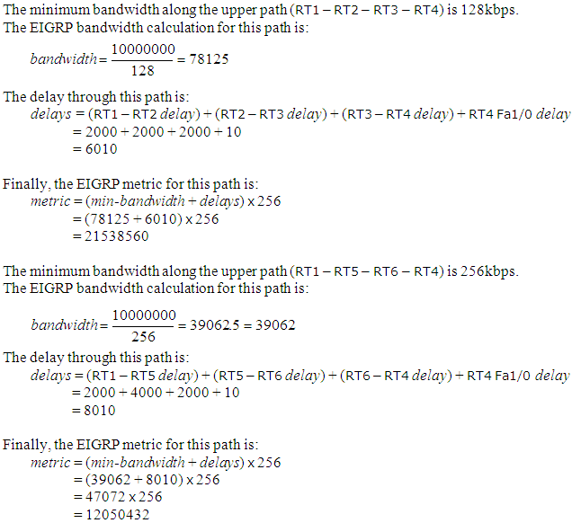
The figure above shows RT1 has 2 paths to reach 172.16.1.0/24. The bandwidth (in kbps) and delay (in tens of microseconds) of all links are also shown.
RT1 chooses the lower path over the upper path due to lower metric value. RT1 installs the route through the lower path with a next-hop of RT5 and a metric of 12050432 in its IP routing table.
RT1#sh ip eigrp topo 172.16.1.0/24
IP-EIGRP (AS 100): Topology entry for 172.16.1.0/24
  State is Passive, Query origin flag is 1, 1 Successor(s), FD is 12050432
  Routing Descriptor Blocks:
  10.10.10.6 (Serial0/1), from 10.10.10.6, Send flag is 0x0
      Composite metric is (12050432/11538432), Route is Internal
      Vector metric:
        Minimum bandwidth is 256 Kbit
        Total delay is 80100 microseconds
        Reliability is 255/255
        Load is 1/255
        Minimum MTU is 1500
        Hop count is 3
The bottleneck along the upper path is the 128kbps link between RT2 and RT3, as this means that the throughput rate through this path would be at a maximum of 128kbps. While the lowest speed along the lower path is 256kbps, allowing the throughput rate up to that speed.
Note: Bandwidth is the largest contributor upon the EIGRP metric. The delay value provides granularity when choosing the best path out from multiple paths with equivalent bandwidth.


No comments:
Post a Comment